A manufacturing specification is the complete build package written after a design is finalized so a workshop technician or prototype supplier can make the product without guesswork. Sending a lone 3D CAD file without matched drawings and material calls causes avoidable rework, wasted stock, and rejected parts before assembly even starts.
In BBC Bitesize’s AQA guide to design briefs and specifications (read 17 October 2026), a manufacturing specification starts with dimensioned drawings, adds a parts list covering materials and finishes for each component, and sets out the order of production including quality assurance, quality control checks, tolerances, equipment and safety notes, and a schedule.
This guide gives student hardware teams a downloadable blank handoff checklist and a worked four-part manifest for the fictional study-desk cable holder introduced in our design brief vs specification worksheet. In that worked manifest, two deliberate flaws (a CAD-to-drawing revision mismatch and an unresolved material entry) show how to reject an incomplete handoff package before fabrication starts. Any tolerance, process setting, or material specification that has not been verified with the maker stays marked TBD.
When do you write a manufacturing specification?
You write a manufacturing specification only after a chosen concept has passed its initial design checks and the geometry is frozen for a specific build round. Writing it too early locks your team into part dimensions before you know whether the concept solves the user problem.
| Document | Core question it answers | Primary contents | When to write or freeze it |
|---|---|---|---|
| Design brief | What problem are we solving, for whom, and in what context? | Problem statement, user situation, project scope, and schedule | At project kickoff, then refined after initial user research |
| Design specification | What measurable outcomes must any candidate solution achieve? | Requirement IDs, observable outcomes, verification methods, and open TBD limits |
After research supplies facts, before selecting a final concept |
| Manufacturing specification | What exact files, materials, steps, and checks let someone else build this chosen design? | Dimensioned custom drawings, structured bill of materials, revision manifest, production sequence, and QC checks | After a specific design is finalized for workshop or prototype fabrication |
BBC Bitesize separates the three documents clearly. The brief states what the client wants, such as a drinks-bottle holder for a bicycle. The design specification lists criteria covering function, materials, performance, aesthetics, environmental issues, and target market so the team can judge ideas. Only after the design is final does the team compile the manufacturing specification for a third party.
Stanford Biodesign’s Prototyping: Build guide (read 17 October 2026, pages 16 to 17) explains why student teams get hurt when they skip interim build documentation to save time. Without a record of each build iteration, teams cannot tell which feature change improved or degraded performance, cannot build consistent replicates for testing, and cannot explain specific features to mentors or external fabricators. Stanford notes that mechanical build records work best when they pair annotated photographs, a parts and materials list, a CAD view, and a link to the underlying CAD files. Just as important, the act of writing the documentation regularly exposes geometry bugs before parts are made.
Stanford Biodesign (pages 11 to 12) also separates stage-specific fabrication expertise. Early prototyping workshops focus on quick iteration and one-off problem solving, whereas manufacturing vendors focus on repeatability across more than 10 identical units. Match the depth of your handoff package to that stage: a student workshop build still needs unambiguous files and material calls, while unknown shop tolerances belong in a TBD review column rather than invented on the drawing.
What belongs in a student hardware handoff package?
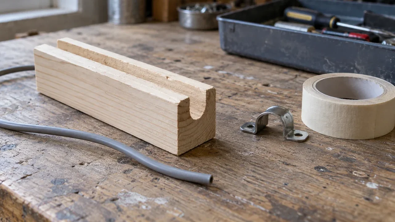
A workable student handoff package joins four records in one folder: a part-by-part bill of materials (BOM), detail drawings for custom parts only, matched 3D CAD exports, and a short order of production with inspection checks.
Carnegie Mellon University’s 16-223 Introduction to Physical Computing course guide on prototype bills of materials, written by Garth Zeglin (read 17 October 2026), defines a BOM as a complete accounting of every component in a manufactured product. Because acquiring materials frequently sets the critical path of a hardware project, the CMU guide splits prototype parts into three groups that require different handoff fields:
| BOM part group (CMU 16-223) | Examples in a student build | Required handoff fields | Drawing requirement (MIT D-Lab II) |
|---|---|---|---|
| Custom-fabricated parts | Milled hardwood base block, laser-cut and bent sheet-metal clip, die-cut base pad | Part ID, short name, form/function description, quantity per assembly, material, finish, fabrication process, where made, 3D CAD file + Rev, 2D drawing PDF + Rev | Requires a dimensioned technical drawing for each custom part |
| Special purchased parts | Non-stock specialty cord grommet, custom-durometer elastomer sheet ordered online | Part ID, short name, item description, vendor name, vendor part number, purchase URL, quantity per assembly, confirmed unit cost or TBD |
No custom fabrication drawing; attach vendor datasheet if fit is critical |
| Stock parts and fasteners | Standard socket-head screws, hex nuts, flat washers held in campus shop bins | Part ID, short name, standard specification (thread, length, head style, material), quantity per assembly | No custom drawing; MIT D-Lab II explicitly excludes standard screws and nuts from detail drawings |
MIT OpenCourseWare’s EC.720J D-Lab II: Design Packet Phase 3 (Implementation) guide (read 17 October 2026) reinforces that split. During detail design, students prepare technical drawings for all critical custom-made components so a third party can understand and fabricate the prototype, while leaving standard off-the-shelf screws and nuts out of the drawing set. In the accompanying fabrication plan, the team lists the required materials, the fabrication processes, and where each component will be made, such as a campus woodshop versus an external sheet-metal service.
Worked example: a desk-accessory handoff manifest that fails review
To see how a handoff checklist prevents wasted shop time, return to the fictional shared study-desk cable holder from our design brief vs specification guide. That earlier worksheet established two testable design requirements:
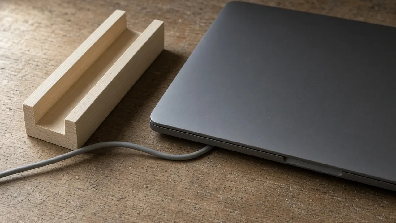
R-01: The charging cable remains on the desk surface through the seated work session described in the brief.R-02: A closed laptop sits flat on the desk beside the accessory with no rock and no lifted corner.
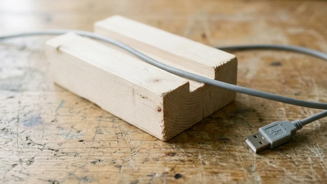
Suppose the student team has selected a four-part assembly (Pkg-CH-2026-10B) to test R-01 and R-02 in three replicate units: a slotted hardwood channel block (CH-101), a formed stainless-steel retaining saddle bracket (CH-102), a non-slip bottom pad (CH-103), and two standard pan-head screws (CH-104). Before handing the folder to the campus workshop technician, the team fills out the handoff manifest below.
Look closely at rows CH-101 and CH-103. This package is rejected at pre-handoff review and marked HOLD before any stock is cut.
| Part ID | Part name & role | Group | Qty / unit | Material & finish | Process & location | 3D CAD file & Rev | 2D drawing PDF & Rev | Linked req & check | Handoff status / blocker (TBD) |
|---|---|---|---|---|---|---|---|---|---|
CH-101 |
Slotted cable-channel base block | Custom | 1 | Kiln-dried beech hardwood, raw sanded, edges chamfered | 3-axis router / mill + drill press, campus woodshop | CH-101_base_RevB.step (saved 16 Oct) |
CH-101_drawing_RevA.pdf (exported 12 Oct) |
R-01, R-02: check cable slot width and flat bottom seating |
HOLD (Blocker 1): 3D CAD is Rev B after hole-spacing edit, but 2D drawing PDF is still Rev A. Slot tolerance TBD with shop technician. |
CH-102 |
Two-hole cable retaining saddle clip | Custom | 1 | Brushed 304 stainless steel sheet, deburred edges; sheet thickness TBD with shop stock |
Laser cut + press-brake bend, campus metal shop | CH-102_saddle_RevB.step (saved 16 Oct) |
CH-102_drawing_RevB.pdf (exported 16 Oct) |
R-01: check hole center distance against CH-101 and cable clearance |
Conditional: Geometry revisions match (Rev B), but available sheet gauge and bend radius remain TBD until confirmed with metal shop. |
CH-103 |
Non-slip underside pad | Custom / Purchased | 1 | "Black rubbery foam" (material family, thickness, durometer, and adhesive backing all TBD) |
Hand-cut or die-cut from adhesive sheet, bench assembly | CH-103_pad_RevA.dxf (saved 12 Oct) |
CH-103_drawing_RevA.pdf (exported 12 Oct) |
R-01, R-02: pad prevents sliding without lifting adjacent laptop |
HOLD (Blocker 2): "Black rubbery foam" is not a purchasable specification. Vendor, part number, thickness, and backing stay TBD. |
CH-104 |
Retaining bracket mounting screw | Stock | 2 | 18-8 stainless steel pan-head wood screw; thread size and length matched to CH-101 pilot hole (TBD) |
Pulled from campus workshop fastener bin | None required (standard hardware) | None required (MIT D-Lab II rule) | Assembly check: screw head seats flush on CH-102 without splitting CH-101 |
Open item: Confirm bin stock size and pilot-hole depth with woodshop lead before drilling CH-101. |
Why this package is rejected before fabrication
First, row CH-101 fails because its 3D CAD file (Rev B) and 2D drawing PDF (Rev A) do not match. On 16 October, a student widened the mounting hole spacing in the 3D model (CH-101_base_RevB.step) to align with the stamped metal saddle bracket (CH-102_saddle_RevB.step), but left the 12 October drawing (CH-101_drawing_RevA.pdf) in the shared handoff folder. NASA’s Appendix M: Configuration Management Plan Outline (read 17 October 2026) organizes configuration control around configuration identification, change management, status accounting, and audit so teams do not build from conflicting baselines. Adapted to a student project, if the 3D STEP file and the 2D PDF drawing carry different revision letters or dates, the technician cannot know which hole spacing is intended. The package stays on hold until CH-101_drawing_RevB.pdf is exported from the Rev B model and verified against CH-102.
Second, row CH-103 fails because "black rubbery foam" is an unresolved material note rather than a specification. That phrase gives a supplier or shop assistant no way to select between closed-cell neoprene, EPDM sponge, polyurethane foam, or solid silicone rubber, nor does it state sheet thickness or pressure-sensitive adhesive backing. Because R-01 depends on desk friction and R-02 depends on overall height beside a laptop, guessing the pad material invalidates the test build. The manifest keeps CH-103 marked TBD with a named owner until the team selects a specific stocked sheet or vendor part number.
How do you check custom part drawings before handoff?
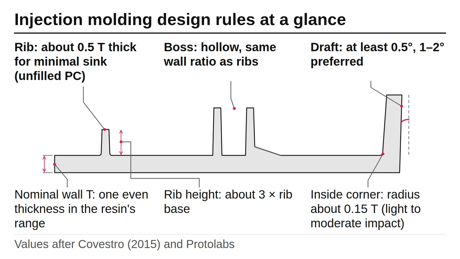
A 3D CAD model defines nominal geometry, while a 2D engineering drawing tells the machinist or technician which surfaces serve as measurement references, what units apply, and which features require close inspection. When deciding whether a part should be printed or machined first, compare process tradeoffs in our 3D printing vs CNC prototyping guide. If you later move a plastic housing toward tooling, use the dedicated injection molding design rules guide for draft, wall thickness, and rib geometry rather than crowding those molding rules into an early bench handoff sheet.
MIT OpenCourseWare’s 2.007 Engineering Drawing and Sketching resource (read 17 October 2026) sets three practical dimensioning rules that student teams can check in five minutes:
- Include every dimension needed to construct the custom part so the drawing permits only one interpretation, with nothing missing and nothing extra.
- Leave out redundant dimensions across the same feature chain. MIT 2.007 warns that if a drawing specifies two sub-feature lengths and also dimensions the overall length across the same chain, those three numbers conflict as soon as tolerances are applied. Omit the redundant overall or sub-feature callout so the drawing shows which dimension actually controls the fit.
- Measure hole locations and slots from a common datum surface (baseline dimensioning) rather than chaining dimensions end to end, and state measurement units and drawing scale in the title block on every sheet.
Use this table to audit each custom drawing PDF before adding it to your handoff manifest:
| Drawing check | What to verify on the sheet | Why a missing or conflicting callout blocks fabrication |
|---|---|---|
| Title block & revision match | Part ID, part name, revision code, date, author, units, and scale match the manifest and 3D CAD filename | Prevents the shop from cutting an outdated revision or reading millimeter numbers as inches |
| Datum selection | Mating surfaces (such as the flat underside of CH-101 and one reference edge) serve as the origin for hole and slot dimensions |
Chain dimensioning stacks tolerances from feature to feature until mounting holes miss the mating bracket |
| Non-redundant dimensions | Each feature is defined once without over-constraining the sum of segments | Redundant dimensions force the machinist to ask which number can float and which number governs inspection |
| Material & finish callout | Specific material family, stock condition, and surface or edge treatment (or an explicit TBD hold note) |
Avoids mystery stock substitutions or sharp unchamfered edges where a cable seats |
| Tolerance discipline | Only verified functional fits carry specific limits; unmeasured general tolerances stay marked TBD for shop confirmation |
Copying arbitrary tight tolerances from a textbook drives up shop setup time without evidence that the function requires them |
How do you write the order of production and quality checks?
BBC Bitesize notes that after drawings and the parts list, a manufacturing specification lays out the order of production (often as a sequence or flowchart) together with quality assurance (QA), quality control (QC), tolerances, equipment and safety notes, and a time scale. In BBC Bitesize’s terminology, quality assurance covers the process conditions that support consistent making (such as trained workshop staff, maintained machines, and verified incoming stock), whereas quality control covers the physical checks performed on the part during and after manufacture.
For our four-part desk cable-holder example, the production sequence and QC table below shows what the team will run after resolving the two HOLD blockers in the manifest. Traceability back to R-01 and R-02 follows the habit from NASA’s Appendix D: Requirements Verification Matrix (read 17 October 2026), which links each requirement ID to its source and verification method. This table is an editorial learning aid for a student workshop build, not a NASA-approved form or a commercial production routing.
| Step # | Operation stage | Part IDs | QA condition, equipment & safety note | QC check & measurement method | Pass criterion or open TBD |
|---|---|---|---|---|---|
| 1 | Incoming stock & file verification | CH-101, CH-102, CH-103, CH-104 |
QA: Confirm Rev B drawing and STEP match for CH-101; confirm selected pad sheet for CH-103 and screw size for CH-104. |
Visual audit against the signed handoff manifest before cutting stock. | All HOLD items cleared; zero revision mismatches between 3D CAD and 2D PDFs. |
| 2 | Base block routing & pilot drilling | CH-101 |
Woodshop router/mill and drill press; clamp workpiece securely, wear eye and hearing protection, and use dust extraction. | Measure overall block height, cable slot width, and pilot-hole center distance from datum edges with calipers. | Cable seats freely in channel; hole center spacing matches CH-102 Rev B (TBD tolerance confirmed with woodshop technician). |
| 3 | Saddle clip cutting, bending & deburring | CH-102 |
Metal shop laser cutter and press brake; deburr inner arch edges so the bracket cannot chafe the cable jacket. | Check hole spacing against datum and pass the target charging cable under the formed arch. | Mounting holes align with CH-101 pilot holes; no burrs contact the cable jacket. |
| 4 | Final assembly & requirement check | Full assembly (CH-101 to CH-104) |
Hand driver on bench; apply confirmed base pad CH-103 to clean underside and fasten CH-102 with two CH-104 screws. |
Run the bench checks linked to R-01 (cable retention on desk edge) and R-02 (closed laptop sits flat alongside). |
Assembly sits flat without rocking (R-02); ready for the session protocol in the physical prototype testing plan. |
Once the workshop builds the replicate units, MIT D-Lab II’s implementation guide points the team directly back to its earlier design specifications to evaluate performance. Plan the session tasks and observation sheets with the physical prototype testing plan, and track material packs, shop hours, and borrowed fixtures in the prototype testing budget worksheet.
Pre-handoff consistency checklist to copy or download
Before you email a zip folder or walk a thumb drive into the campus machine shop, run this six-point stop-release audit. You can also download the blank Markdown handoff checklist to keep inside your project repository.
- Confirm that the package header lists the specific design specification requirement IDs (such as
R-01andR-02) that this build round will test, and freeze concept changes for this revision. - Verify that the manifest accounts for every custom-fabricated part, special purchased component, and stock fastener with quantities per assembly (CMU 16-223).
- Check that every custom part carries the exact same revision code and export date on both its 3D CAD file and its 2D drawing PDF (NASA Appendix M baseline habit).
- Attach datum-dimensioned drawings with units and scale for all custom-made components while omitting unnecessary custom drawings for standard screws and nuts (MIT D-Lab II and MIT 2.007).
- Include annotated build photos or assembly views alongside a link to the underlying CAD so a technician or teammate can see how the parts assemble (Stanford Biodesign).
- Mark every unverified material grade, stock thickness, or shop tolerance as
TBDwith a named owner rather than filling in a guessed number or a vague note like"black rubbery foam".
How this guide was compiled and its limits
Compiled on 17 October 2026 from seven public educational and engineering reference sources retrieved that day: BBC Bitesize’s AQA GCSE Design and Technology revision guide on design briefs and specifications, Stanford Mussallem Center for Biodesign’s Prototyping: Build guide, Carnegie Mellon University IDeATe’s 16-223 Prototype Bill of Materials assignment guide by Garth Zeglin, MIT OpenCourseWare’s EC.720J D-Lab II Design Packet Phase 3: Implementation, MIT OpenCourseWare’s 2.007 Engineering Drawing and Sketching notes, and NASA Systems Engineering Handbook Appendix D and Appendix M.
The four-part desk cable-holder manifest (Pkg-CH-2026-10B), the deliberate Rev B versus Rev A file mismatch, and the unresolved "black rubbery foam" blocker are original editorial teaching examples constructed for this article. They do not report physical test results, vendor quotes, or certified manufacturing routings, and NASA’s appendices are cited solely as transferable habits for requirement traceability and revision control. This checklist supports student and early formative hardware handoffs; it does not provide universal numeric tolerances, regulatory compliance advice, safety certification, or mass-production readiness.