Design for Manufacturing (DFM) is the engineering discipline of structuring a product’s architecture, custom component geometry, material specifications, and datum tolerances around the physical capabilities and economics of the target production system before committing to hard tooling. Treating DFM as a last-minute draft-angle check after freezing CAD geometry causes costly mold steel rework, rejected first-article parts, tolerance stack interference, and assembly line bottlenecks.
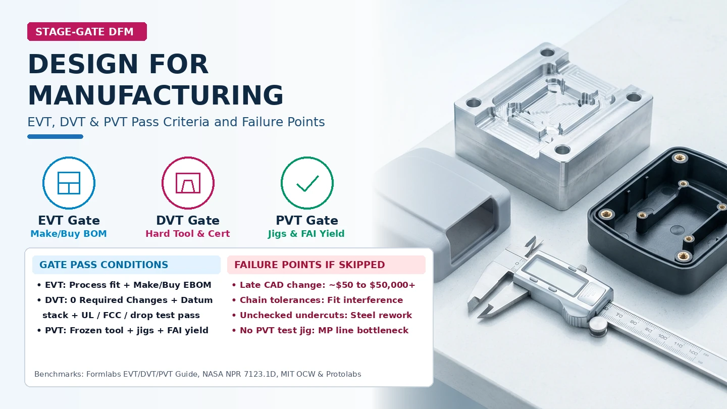
To understand what Design for Manufacturing is in real hardware development, teams must separate individual part moldability from stage-gate industrialization. Across Engineering Validation Testing (EVT), Design Validation Testing (DVT), and Production Validation Testing (PVT), DFM governs four sequential engineering anchors: matching materials and processes during the Make-or-Buy split, locking datum-referenced tolerance chains, resolving hard-tool shutoffs and regulatory compliance, and validating factory assembly jigs, PCB test fixtures, and first-pass line yield.
While quantitative feature-sizing formulas for plastic housings—such as nominal wall T, 0.40T–0.60T rib root ratios, volcano boss relief, and VDI 3400 or Mold-Tech draft adders—live in our companion reference on injection moulding design guidelines for walls, draft, and ribs, this guide maps the complete DFM process across hardware stage gates. Below, we cover how DFM differs from Design for Assembly (DFA), how the five principles of DFM prevent hardware failures, what entrance inputs and exit deliverables govern EVT, DVT, and PVT, and how to audit your release package with a gate-by-gate verification checklist.
Quick stage-gate DFM summary
| Hardware stage gate & systems parallel | Typical build quantity & tooling state (Formlabs benchmark) | Primary DFM focus & engineering verification | Mandatory gate exit deliverables | Dominant failure mode if skipped |
|---|---|---|---|---|
| Pre-EVT (POC & Alpha) (Concept & Subsystem Feasibility) |
1–5+ focused units; foam, 3D prints, breadboards, machine shop (MIT OCW EC.720J) |
Part-count reduction; custom drawings restricted to custom parts (no custom drawings for standard OTS screws) | Testable design specification; candidate materials & shop-class list; initial part-count reduction audit | Entering detail CAD with redundant parts or custom-drawing catalog fasteners |
| Gate 1: EVT (Engineering Validation Test / NASA PDR Table G-6) |
20–50 units (3–6 mo); precision CNC, additive, silicone/3D-printed soft tooling |
Architecture-level DFM: 100% Make-or-Buy split; process–volume matching; hot-stake PCB power/thermal/EMI tests | Baselined preliminary EBOM for Contract Manufacturer (CM) RFQs & First Shots (FS); OPEN item closure schedule |
Quoting an unmanufacturable architecture or incompatible material–process pair (~$500–$1,000 prototype rework) |
| Gate 2: DVT (Design Validation Test / NASA CDR Table G-7) |
50–200 units (1,000+ on large runs, ~3 mo); first hard tooling or aluminum bridge molds |
Detail industrialization: zero supplier Required Changes; signed-off Advisories; sliders/cams, gate/ejector layout, datum stacks, FCC/UL/CE/RoHS & environmental tests | Frozen build-to Technical Data Package (TDP); verified hard-tooled samples; closed Engineering Change Orders (ECOs) |
Cutting steel with unresolved undercuts, chain-dimension interference, or failed EMC/drop tests (up to $50,000+ tool rework) |
| Gate 3: PVT (Production Validation Test / NASA PRR Table G-8) |
500+ units or >= 5% of first MP run (~1 mo); 100% frozen hard tooling |
Line & yield readiness: multi-station assembly jigs, PCB panel test fixtures, EBOM-to-MBOM alignment, FMECA, FAI, and QA/QC plans | Signed First Article Inspection (FAI); single-source mitigation; Green-light gate metrics on line speed, scrap & daily yield | Unfixtured assembly bottlenecks, uncalibrated PCB test benches, or high scrap halting Mass Production (5,000+ units) |
1. What Is Design for Manufacturing (DFM)—and Why a Draft Check Alone Is Not DFM
Answering what is design for manufacturing requires distinguishing part-level geometry rules from system-level industrialization. In hardware engineering, DFM is the systematic verification that every custom component, sub-assembly interface, bill of materials, and quality control step can be fabricated repeatedly within target cost and yield constraints at the intended production volume.
DFM vs. DFA vs. DFMA: Separating Part Fabrication from Assembly Architecture
Industry literature frequently groups manufacturability into three related terms, each governing a distinct layer of the physical product:
- Design for Manufacturing (DFM): Focuses on the fabrication feasibility, process physics, material compatibility, tooling complexity, and unit cost of individual components. DFM asks whether a specific metal bracket, molded polycarbonate bezel, or multilayer printed circuit board (PCB) can be machined, formed, molded, or etched without defects, excessive tool wear, or tight-tolerance scrap.
- Design for Assembly (DFA): Focuses on how individual parts come together on the workbench or factory floor. DFA minimizes total part count, standardizes fastener types and tool driver sizes, enforces self-locating or poka-yoke (mistake-proof) geometry, and eliminates blind or awkward assembly motions. In MIT OpenCourseWare’s EC.720J D-Lab II: Design Packet Phase 3: Implementation (Spring 2010, retrieved October 2026), engineers evaluating a functional prototype are instructed to challenge every sub-assembly: ask how to make the device cheaper, faster, and better by lowering the part count or removing excess material so the mechanism is as simple as possible.
- Design for Manufacturing and Assembly (DFMA): Combines DFM and DFA into a unified early-stage discipline. A pure DFA decision—such as merging three stamped sheet-metal brackets into a single complex die-cast housing—reduces fastener count and assembly labor, but only succeeds if the resulting housing passes DFM checks for die-pull direction, wall uniformity, and machining datum access.
The Exponential Cost of Late Design Changes ($50 vs. $500–$1,000 vs. $50,000+)
Deferring DFM until after a 3D CAD assembly is labeled “complete” exposes hardware teams to exponential rework costs. As Formlabs documents in Validation Testing in Product Development: From POC to EVT, DVT, PVT, and Mass Production (published June 4, 2021; retrieved October 2026), iteration expenses escalate by orders of magnitude as a product advances across maturity gates:
- Concept Sketches and Foam Mockups (
~$50in materials): During initial Proof of Concept (POC) exploration, modifying part geometry or splitting an enclosure shell requires only shop foam, cardboard, or a CAD rebuild costing roughly $50 in raw materials. - Functional Rapid Prototypes (
~$500 to $1,000): Once an engineering team integrates 3D-printed housings, off-the-shelf buy-in components, and vacuum-cast urethane overmolds during alpha and early beta builds, spinning a new hardware revision typically costs on the order of $500 to $1,000. - Production Tooling Modifications (
Up to $50,000+and weeks or months of delay): Discovering a wall-thickness sink defect, a missing regulatory label recess, a mating-part tolerance collision, or an unmoldable undercut after cutting production mold steel can cost up to $50,000 or more in welding, EDM re-machining, or replacement cavity blocks while delaying commercial launch by multiple weeks or months.
Rule of thumb (Pre-Tooling Architecture Gate): If a product’s Make-or-Buy component split, target fabrication process, datum tolerance scheme, and regulatory test envelope have not been verified on functional prototypes, freeze hard-tooling expenditure; resolving an architectural defect in CAD or soft prototyping ($50–$1,000) prevents a $50,000+ steel tooling write-off at DVT.
Refuting the “Draft-Angle Fallacy”
A common failure mode among student teams and first-time hardware startups is equating DFM entirely with adding 1° to 2° of draft and uniform 2.0 mm walls to an injection-molded enclosure. While polymer rheology and mold release rules are vital for plastic part tooling (see our quantitative lookup tables in injection moulding design guidelines: wall thickness, rib ratios, boss relief, and texture draft tables), a housing with flawless draft angles still fails DFM if:
- The chosen resin fractures during drop testing or fails UL 94 flammability or FCC / CE electromagnetic compatibility (EMC) qualification at DVT;
- Chain-dimensioned mounting bosses accumulate bilateral tolerance error and crush the internal display or PCB assembly;
- The Contract Manufacturer (CM) has no locating datums or test-point access to place the PCB into a panelized bed-of-nails test fixture during PVT.
Takeaway: Treat DFM as a multi-stage engineering verification system spanning process selection, material pairing, datum tolerancing, and factory testability rather than a one-time plastic geometry check.
2. The Five Principles of Design for Manufacturing Mapped to Hardware Failure Modes
To apply design for manufacturing principles systematically across mechanical, electromechanical, and enclosure assemblies, manufacturing engineers audit five core domains. When any single domain is overlooked during detail design, predictable failure modes emerge during quoting, first-shot sampling, or pilot assembly.
1. Process Selection and the Make-or-Buy Split
Every component in an assembly must be matched to a fabrication process suited to its target production volume, geometric complexity, and required precision. In MIT OpenCourseWare’s EC.720J D-Lab II implementation guide, detail design requires three explicit lists alongside technical drawings: a materials list, a list of fabrication processes required for each component, and the designated manufacturing site class (such as a small-scale machine shop versus a large plastics factory).
Simultaneously, MIT D-Lab II enforces a strict boundary on engineering documentation: produce technical drawings only for critical custom-made components (in SolidWorks, Creo/Pro-Engineer, or AutoCAD), and never draft custom part drawings for standard off-the-shelf (OTS) hardware such as machine screws, hex nuts, washers, or catalog standoffs. In Formlabs’ EVT workflow, this discipline formalizes into a complete Make-or-Buy analysis across the Bill of Materials (BOM), isolating custom-tooled “Make” parts from catalog “Buy” items before sending Requests for Quotation (RFQs) to contract manufacturers.
2. Material–Process Compatibility
Selecting a material requires balancing functional service demands—mechanical strength, elastic modulus, heat deflection temperature, dielectric strength, chemical resistance, and flammability—against how that material behaves inside the chosen fabrication process. In Protolabs’ manufacturing analysis documentation (Improve Part Design with DFM Feedback, retrieved October 2026), wall thickness limits and cavity fill pressures vary directly by polymer family. Specifying a high-viscosity polycarbonate for a thin-walled housing without running a melt-flow pressure check results in short shots (incomplete cavity fill), frozen flow lines, or excessive injection pressure that flashes the parting line.
3. Part Geometry and Tooling Action Simplicity
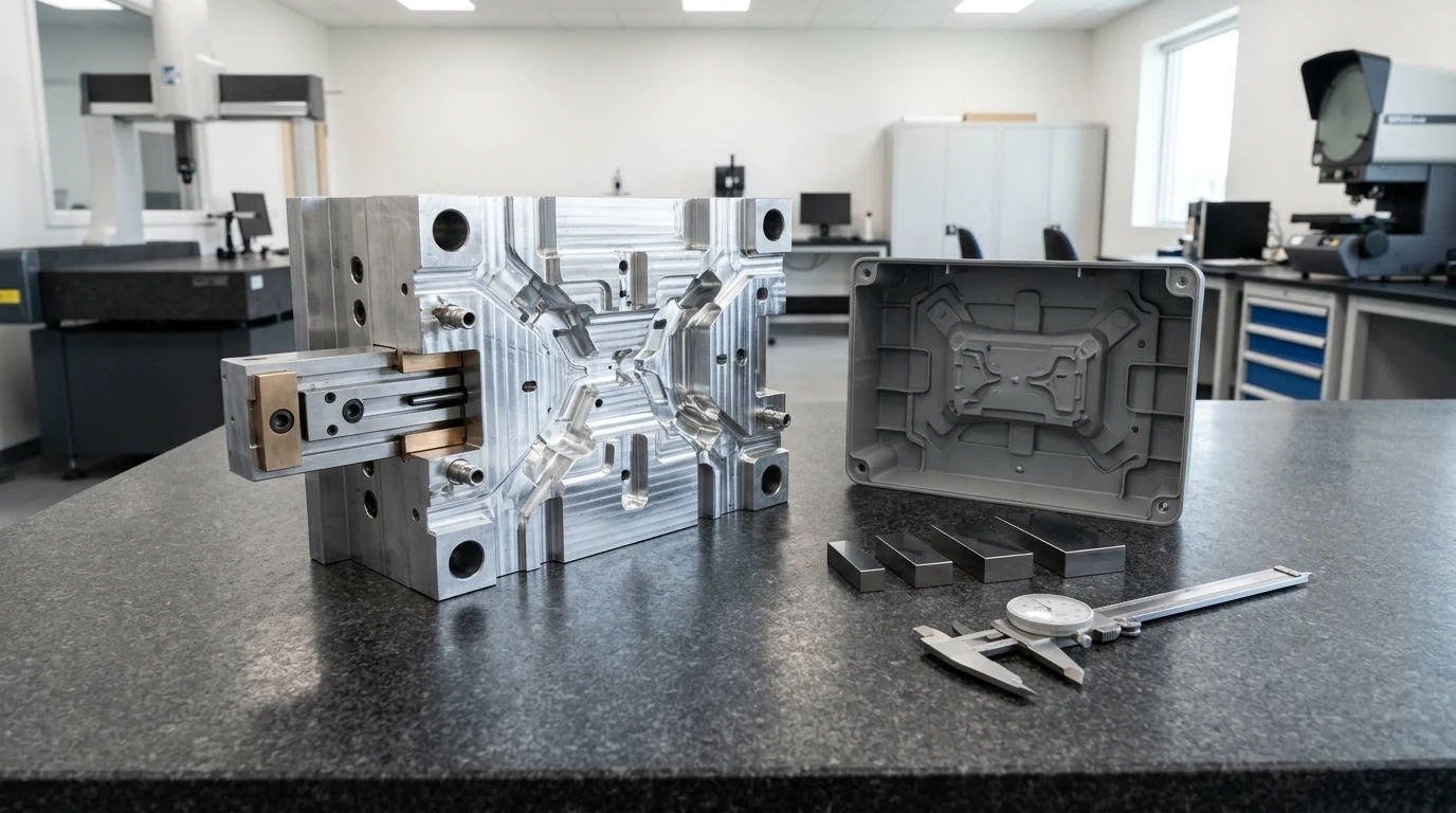
Within the selected process, component geometry must allow tooling cutters, punches, or mold cores to form and release the part with minimal mechanical complexity. In injection molding and die casting, features that cross the primary line of draw—such as side-wall connector ports, snap-fit windows, or radial bosses—create undercuts. Resolving an undercut requires either redesigning the feature into a pass-through “kiss-off” shutoff along the parting plane or adding moving mold mechanisms such as side-action cores, angled lifters, sliders, or cams (Formlabs, June 2021; Protolabs, October 2026). Every moving slider adds mold machining cost, introduces witness lines around the sliding block perimeter, and creates a mechanical wear point over high-volume cycling.
4. Datum-Referenced Dimensioning and Functional Tolerancing (ASME Y14.5)
How a part is dimensioned on a 2D drawing directly governs how a machinist or toolmaker fixtures and inspects it. MIT OpenCourseWare’s 2.007 Design and Manufacturing I: Engineering Drawing and Sketching handbook (Prof. Daniel Frey, Spring 2009; retrieved October 2026) establishes three foundational DFM dimensioning rules:
- Originate dimensions from a common datum surface rather than chain dimensioning: Repeatedly measuring point-to-point in series (chain dimensioning) causes machining and measurement inaccuracies to accumulate across every step. Originating feature locations from a single reference plane (datum surface dimensioning) eliminates series stack-up and matches the sequence in which a machinist cuts and inspects the part.
- Eliminate redundant dimensions: Including more dimensions than necessary to define a geometry creates over-constrained tolerance conflicts when bilateral allowances add up in competing ways. Where an overall length is already fixed by internal feature dimensions and a boundary radius, mark the overall length explicitly as a reference dimension (
REF) so the shop knows it is informational rather than a competing inspection requirement (MIT OCW 2.007). - Apply Geometric Dimensioning and Tolerancing (GD&T) for functional interchangeability: As stated in the American Society of Mechanical Engineers’ public overview for ASME Y14.5-2018 (R2024) (Dimensioning and Tolerancing, retrieved October 2026), the Y14.5 standard defines the authoritative engineering language for specifying datum reference frames, degrees of freedom, feature-of-size limits, and profile, orientation, position, and form controls across both 2D drawings and 3D digital data files. Applying functional datum references reduces shop-floor guesswork and guarantees part interchangeability. (For a worked one-dimensional worst-case clearance stack
G = H - B - Tbetween mating enclosure surfaces, see our guide on mechanical design engineer DFM handover skills before tooling.)
5. Environment, Compliance, and Testability (DFM + DFT)
A manufacturable product must survive its operating environment, pass mandatory regulatory certifications, and support high-speed factory testing (Design for Testability, DFT). On the mechanical side, Formlabs notes that pre-production DVT units must pass environmental chamber cycling, thermal shock, salt fog corrosion, vibration, electrostatic discharge (ESD), drop testing, and applicable agency approvals (FCC, UL, CE, RoHS, or FDA). On the electronics side, printed circuit boards must follow IPC-2221 and IPC-A-600 layout rules to prevent five recurring PCB DFM failures:
- Non-standard or inaccurate component land-pattern footprints that cause solder tombstoning or bridging;
- Insufficient copper-to-board-edge clearance that exposes inner planes during depanelization routing;
- Inadequate component-to-component spacing that blocks automated optical inspection (AOI) or rework nozzles;
- Unoptimized PCB panelization arrays that waste FR-4 laminate or twist during reflow soldering;
- Missing test pads or keep-out zones for panelized bed-of-nails pogo-pin fixtures at PVT (
Formlabs, June 2021).
Five DFM principles vs. hardware failure modes matrix
| DFM principle | Core engineering verification | Primary standard or authority source | Dominant failure mode if violated | Prevention & stage-gate control |
|---|---|---|---|---|
| 1. Process & Make-or-Buy Fit | Match process to volume (1–50 vs. 5,000+); separate custom “Make” drawings from “Buy” OTS hardware |
MIT OCW EC.720J & Formlabs (EVT) |
Specifying 3-axis CNC features on a high-volume molded housing, or wasting hours drafting catalog M3 screws | Complete 100% Make-or-Buy BOM split at EVT; restrict 2D drawings to custom parts |
| 2. Material–Process Compatibility | Verify melt flow, shrinkage, and forming limits alongside thermal, mechanical, and chemical specs | Protolabs (ProtoFlow) & Formlabs (DVT) |
Short shots, weld lines, or chemical cracking when an incompatible resin is paired with thin-wall tooling | Declare exact resin grade upfront during quoting; review cavity fill pressure map before DVT |
| 3. Geometry & Tooling Simplicity | Align features to mold draw; replace avoidable undercuts with pass-through shutoffs; bound sliders/cams | Protolabs & Formlabs (EVT → DVT) |
Locked parts that cannot eject, or expensive side-action sliders that flash and slow press cycle times | Triage all supplier Required Changes to zero and sign off on Advisories before cutting steel |
| 4. Datum Dimensioning & GD&T | Dimension from functional datum surfaces; omit redundant callouts (REF); define datum frames |
MIT OCW 2.007 & ASME Y14.5-2018 (R2024) |
Chain-dimension tolerance accumulation causing PCB-to-enclosure interference or conflicting shop limits | Replace chain dimensions with common datum planes and verify worst-case interface stacks pre-DVT |
| 5. Environment, Compliance & DFT | Design for thermal, drop, ESD, and UL/FCC/CE/RoHS tests plus PCB panelization and pogo-pin access | Formlabs (DVT/PVT) & IPC-2221 / IPC-A-600 |
Failing EMC/drop certification after hard tooling is cut, or shipping PCBs that cannot be panel-tested | Run pre-compliance EMI/thermal scans at EVT, full cert tests at DVT, and panel test jigs at PVT |
Takeaway: Audit all five DFM pillars—process/Make-Buy fit, material rheology, tooling draw geometry, common-datum tolerancing, and environmental/test-fixture compliance—as a unified system before approving DVT mold steel.
3. Where DFM Happens: Stage-Gate Checkpoints Across POC, EVT, DVT, and PVT
Understanding how to design a product for manufacturing requires anchoring DFM tasks onto a gated project timeline. In The Stage-Gate Model: An Overview (Stage-Gate International, Dr. Robert G. Cooper; retrieved October 2026), product development is divided into work Stages separated by forward-looking decision Gates. Every gate comprises three governance elements:
- Gate Deliverables: Visible technical and operational outputs specified in advance that the project team brings to the review.
- Gate Criteria: The readiness and business-value benchmarks against which the deliverables are judged.
- Gate Outputs: A formal Go, Kill, Hold, or Recycle decision paired with an explicit commitment of budget, staffing, and schedule for the next stage.
In aerospace and defense systems engineering, NASA NPR 7123.1D Appendix G (Life-Cycle and Technical Review Entrance and Success Criteria, effective July 5, 2023 to July 5, 2028; retrieved October 2026) structures technical gates into two mandatory verification columns: Entrance Criteria (the baselined plans, drawings, and discrepancy closure schedules that must be complete to hold the meeting) and Success Criteria (the engineering maturity statements that must be proven to release fabrication or production funds). While NPR 7123.1D is mandatory only for NASA programs and explicitly directs teams to tailor review products to project scope (Section G.1.2), its progression from Preliminary Design Review (PDR) to Critical Design Review (CDR) and Production Readiness Review (PRR) maps directly onto commercial hardware’s EVT, DVT, and PVT validation gates. (For the broader 5-stage NPD framework and destructive-test prototype budgeting formula, see our guide to product design stage-gate milestones from concept to trial run.)
Pre-EVT: Proof of Concept (POC) and Alpha Prototyping
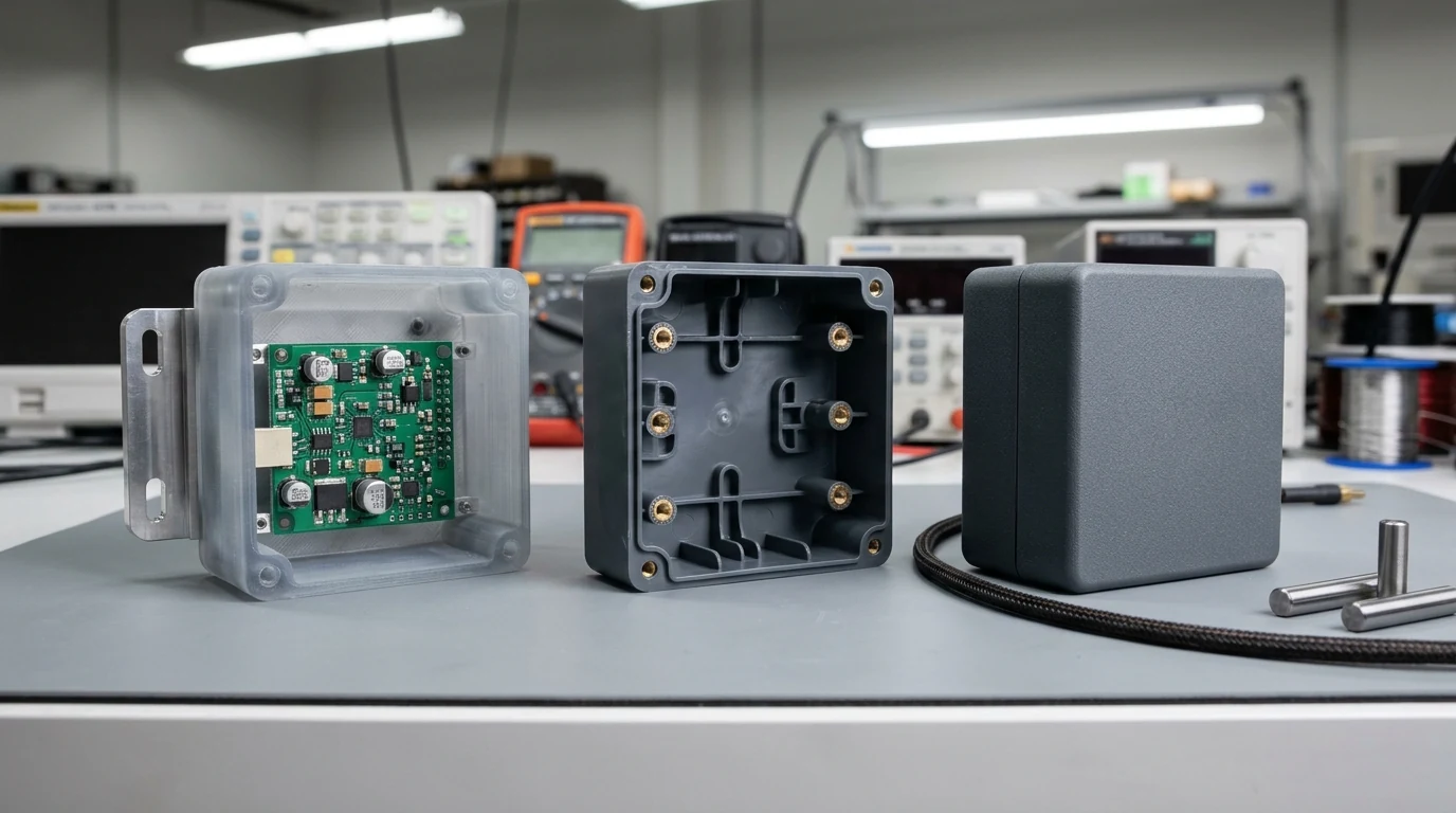
After product planning establishes the Product Requirements Document (PRD), teams build Proof of Concept (POC) and Alpha prototypes (Formlabs, June 2021). These early builds include non-form-factor (NFF) breadboards powered by development kits (such as Arduino or Raspberry Pi assemblies), “looks-like” industrial design foam models, and “works-like” mechanical sub-assemblies.
- Typical Build Scope:
1 to 5+focused prototypes over3 months to 3+ yearsdepending on R&D complexity (Formlabssummary matrix). Formlabs notes that complex ergonomic or physical inventions often require extensive alpha iteration—citing IDEO’s 80 foam models to refine the 1987 Microsoft mouse and James Dyson’s 5,127 cyclone vacuum prototypes over 15 years. - DFM Boundary at Pre-EVT: As MIT OpenCourseWare’s EC.720J D-Lab II packet emphasizes, POC parts are fabricated individually and do not yet use final production tooling. The DFM mandate before exiting Alpha into EVT is to prove core physics, eliminate unnecessary parts, separate custom components from off-the-shelf hardware, and record the target fabrication process and shop class for every custom part.
Gate 1: Engineering Validation Test (EVT) — Architecture-Level DFM
In Formlabs’ hardware validation framework, EVT merges the separate “looks-like” and “works-like” alpha models into the first production-intent “beta” engineering prototype configured in the final form factor.
- Typical Build Quantity & Duration: Approximately
20 to 50 unitsover3 to 6 months, fabricated via high-precision CNC machining, additive manufacturing (SLA/SLS), or soft tooling such as silicone urethane casting or 3D-printed injection molds (Formlabs, June 2021). - Core DFM Activities: EVT is defined by architecture-level DFM (
Formlabs). The engineering team completes a Make-or-Buy analysis for every part in the assembly, performs component engineering on custom parts, and compiles a structured Engineering Bill of Materials (EBOM) to issue RFQs to Contract Manufacturers (CMs) for first assembly line planning and First Shots (FS) tooling preparation. Electronics move onto industrial “hot-stake” PCBs to undergo baseline power, thermal, and EMI testing. - NASA Systems Parallel (
PDR, Table G-6): Parallels NASA’s Preliminary Design Review, where entrance criteria require a baselined producibility/manufacturability program plan, a preliminary engineering drawing tree, interface control documents, and EMI/EMC control plans, and success criteria verify that “Manufacturability has been adequately included in design” and all remaining open technical items have scheduled closure plans (NPR 7123.1DAppendix G, Lines 285–319).
Gate 2: Design Validation Test (DVT) — Hard Tooling & Detail Industrialization
Once the EVT architecture passes functional verification, DVT industrializes every detail of the product using production-intent processes (Formlabs, June 2021).
- Typical Build Quantity & Duration: Typically
50 to 200 units(scaling to1,000+ unitson large consumer programs) over approximately3 months, molded or formed on the Contract Manufacturer’s first hard tooling or aluminum bridge molds (Formlabs). - Core DFM Activities: DVT optimizes part and tool details to verify mass-production yields. Engineers and toolmakers validate surface finishes, resin shrinkage, tight tolerances, mold configurations (sliders, cams, lifters, parting lines, and gate/ejector pin witnesses), and production joining methods (such as heat-staking PCBs onto molded plastic bosses via integrated rivets). Electronics undergo final PCB debugging and denoising. Hard-tooled DVT units are then subjected to exhaustive environmental and regulatory qualification: thermal cycling, salt fog corrosion chambers, vibration, ESD, biocompatibility or chemical resistance, drop testing, accelerated aging, and FCC, UL, CE, RoHS, or FDA certification testing (
Formlabs). - Why Skipping DVT Fails: Formlabs notes that while some teams attempt to compress schedules by ordering PVT-scale hard tooling at the end of EVT—trying to satisfy EVT prototype goals and DVT hard-tooling yield checks in one jump—committing mass-production tooling capital before resolving DVT environmental, EMC, and mold-tuning findings carries extreme financial risk and is strongly discouraged.
- NASA Systems Parallel (
CDR, Table G-7): Parallels NASA’s Critical Design Review, which requires baselined product build-to specifications, a complete Technical Data Package (TDP), fabrication/assembly/integration/test plans, and material property stress analyses before authorizing full-scale fabrication (NPR 7123.1DAppendix G, Lines 328–385).
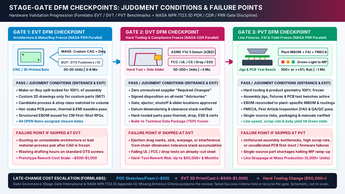
Gate 3: Production Validation Test (PVT) — Frozen Tooling, Line Fixtures & Yield Freeze
PVT is the final gate prior to commercial ramp-up. At the entrance to PVT, hard tooling and product design are 100% frozen—no further changes to part geometry or production molds are permitted (Formlabs, June 2021).
- Typical Build Quantity & Duration:
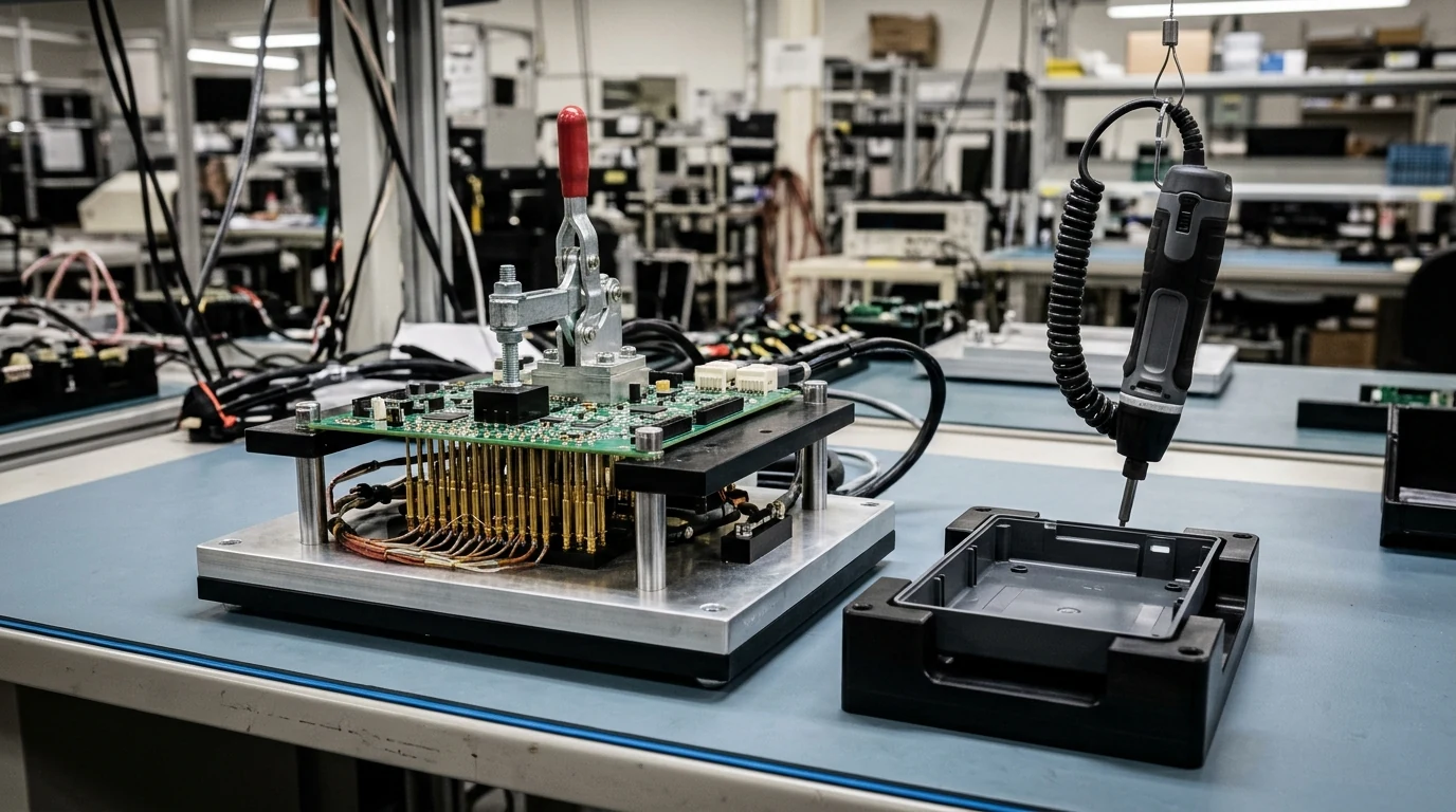
500+ unitsor at least5%of the first production run over roughly1 month, executed on the Contract Manufacturer’s actual assembly line to produce sellable commercial inventory (Formlabs). - Core DFM & Industrialization Activities: PVT shifts focus from part geometry to production line stabilization. All multi-station mechanical assembly jigs, fixtures, and panelized PCB test benches must be installed and validated before the production pilot commences. The CM and engineering team execute Failure Mode, Effects, and Criticality Analysis (FMECA), First Article Inspection (FAI), and in-process QA/QC audits; resolve single-source component supply risks; verify first-boot electronics and firmware flashing; and finalize master-carton packaging and user manuals. Line readiness is tracked via a Red / Orange / Green gate scorecard measuring line speed, operator takt time, daily yield, and scrap rate. When all metrics reach the Green state, the gate opens to Mass Production (MP, typically
5,000+units) with ongoing Early Field Failure Analysis (EFFA) (Formlabs). - NASA Systems Parallel (
PRR, Table G-8): Parallels NASA’s Production Readiness Review, which requires resolved development nonconformances, certified raw materials, critical process control limits, available special tools and test equipment in proper quantities, alternate sources for key items, qualified suppliers, and planned in-process and end-item inspections (NPR 7123.1DAppendix G, Lines 393–429).
Quantitative PVT Pilot Sizing and First-Pass Yield Accounting
To size a PVT pilot batch (N_PVT) and evaluate whether line scrap and rework meet the Green-light gate threshold for Mass Production (N_MP), manufacturing engineers combine Formlabs’ >= 5% pilot quantity benchmark (500+ units minimum for consumer runs) with first-pass yield (Y_FPY) accounting:
1. Target PVT Pilot Batch Size (Formlabs 5% / 500-Unit Rule):
   N_PVT = max(N_min_gate, 0.05 x N_MP)

2. First-Pass Line Yield (Y_FPY) and Scrap Rate (R_scrap):
   Y_FPY   = (N_PVT - N_scrap - N_rework) / N_PVT
   R_scrap = N_scrap / N_PVT
   N_sellable_first_pass = N_PVT x Y_FPY

Worked Benchmark Example (First Mass Production Order N_MP = 12,000 Units, N_min_gate = 500):
  - Required PVT pilot run: N_PVT = max(500, 0.05 x 12,000) = 600 units on frozen hard tooling.
  - Pilot line results: 12 housings scrapped for cosmetic/dimensional nonconformance (N_scrap = 12)
    and 18 assemblies routed to off-line rework for torque/firmware re-test (N_rework = 18).
  - Scrap rate: R_scrap = 12 / 600 = 0.020 (2.0% scrap).
  - First-pass line yield: Y_FPY = (600 - 12 - 18) / 600 = 570 / 600 = 0.950 (95.0% first-pass yield),
    releasing 570 immediate sellable units while FMECA corrective actions close the 3.0% rework loop before MP.
Takeaway: Align every DFM check to its proper gate—freeze Make-or-Buy and process selection at EVT, resolve hard-tool sliders, datum stacks, and certifications at DVT, and lock assembly jigs, FAI, and first-pass yield on frozen tooling at PVT.
4. How to Triage a Supplier DFM Report Before Cutting Steel (Required Changes vs. Advisories)
Between exiting EVT and cutting DVT molds, the mechanical team submits a 3D CAD assembly (STEP) and 2D drawing package to the injection molder or precision machinist. Understanding how to read and disposition the resulting supplier DFM analysis prevents both premature steel cutting and unnecessary CAD rework.
1. Required Changes vs. Advisories in Automated 3D CAD Analysis
Using Protolabs’ interactive manufacturing analysis workflow (Navigating Manufacturing Analysis, retrieved October 2026) as a representative industry benchmark, supplier quoting systems evaluate uploaded 3D CAD geometry and classify findings into two distinct tabs:
- Required Changes (Hard Tooling Blockers): Geometric features that physically cannot be machined into the mold block or cannot eject from the cavity—such as trapped internal undercuts or external side-actions that exceed the toolmaker’s side-core envelope (in Protolabs’ rapid injection-molding system, maximum side-core dimensions are
8.419 in. width × 2.377 in. height × 2.900 in. pull). Required changes must be modified in the 3D CAD model before parts can be ordered or steel can be cut. - Advisories (Process & Yield Risk Warnings): Non-blocking manufacturability flags where the part can still be fabricated “as-is,” but geometry deviates from optimal molding practice. In Protolabs’ system, advisories cover vertical walls with zero or minimal draft (Protolabs recommends at least
0.5°draft on all vertical faces,2°draft where possible,3° minimumfor light bead-blast finishPM-T1, and5° minimumfor medium bead-blast finishPM-T2), thin wall regions prone to short shots, thick cross-sections prone to sink, and elevated cavity fill pressures flagged by ProtoFlow melt-flow simulation. Ignoring an advisory allows tooling to proceed, but transfers the risk of ejection drag marks, stress distortion, sink depressions, or cycle delays onto the buyer.
Rule of thumb (Supplier DFM Triage): If a supplier DFM report flags a Required Change, update the 3D CAD geometry and re-run the analysis before releasing purchase orders; if it flags an Advisory on a functional or cosmetic surface, either modify the draft/wall geometry or record a signed engineering waiver accepting the cosmetic or dimensional risk prior to DVT gate closure.
2. Three Pre-Tooling Sign-Offs Every Engineer Must Complete in the Quote Portal
Before authorizing DVT mold fabrication, verify three supplier-side settings that automated geometry checkers cannot decide on their own (Protolabs, October 2026):
- Explicit Resin Selection (Overriding the Default ABS Assumption): In Protolabs’ quoting workflow, uploading a 3D CAD file without specifying a polymer automatically defaults the analysis to ABS plastic. Because recommended wall thicknesses and ProtoFlow viscosity curves depend on the exact polymer family, always set the production resin grade upfront so thin/thick wall warnings reflect your actual material.
- Gate and Ejector Pin Witness Layout: Once a 3D model is submitted for order, supplier mold designers place the injection gate (where molten polymer enters the cavity) and ejector pins (which push the cooled part off the core). Review and approve this layout before mold machining begins so gate vestige stubs and circular ejector pin witness marks land on hidden internal B-side faces rather than cosmetic A-side surfaces or precision datum pads.
- 2D Datum Drawing and
OPENTolerance Reconciliation: A 3DSTEPfile communicates nominal geometry, but 2D drawings govern functional tolerances (ASME Y14.5-2018 R2024), thread callouts, and surface finish codes. Check that every critical interface is dimensioned from a common datum surface without redundant callouts (MIT OCW 2.007), and verify that any unconfirmed shop tolerance in your manufacturing specification handoff checklist is resolved with the supplier’s applications engineer before removing itsOPENhold tag.
3. Reconciling the Engineering BOM (EBOM) into a Plant-Specific Manufacturing BOM (MBOM)
Fixing individual CAD parts does not complete factory handoff. As enterprise PLM documentation from PTC highlights, a major source of ramp-up delay is the structural gap between product engineering’s Engineering Bill of Materials (EBOM) and the factory planner’s Manufacturing Bill of Materials (MBOM).
- The Engineering BOM (
EBOM) organizes parts by functional design discipline (for example, grouping all mechanical housings, all fasteners, and the bare PCB assembly as flat engineering lists). - The Manufacturing BOM (
MBOM) restructures those exact components into the sequence of sub-assemblies, phantom kits, adhesives, thread-locking compounds, packaging inserts, and station-by-station shop-floor routings required by a specific factory plant.
During the DVT-to-PVT transition, product and manufacturing engineers must synchronize EBOM-to-MBOM transformations under unified Engineering Change Management (ECM / ECO) so that any late DVT part revision updates the corresponding factory work instructions, assembly jigs, and ERP/MES inspection plans simultaneously.
Supplier DFM triage and factory handoff matrix
| Pre-tooling review item | Supplier / factory classification | Engineering action required before DVT / PVT | Consequence of releasing without closure |
|---|---|---|---|
| Unmachinable undercut or oversized side-action | Required Change (Protolabs) |
Redesign into a parting-line pass-through shutoff or scale feature within side-core envelope (8.419 × 2.377 × 2.900 in.) |
Toolmaker places order on hold; mold steel cannot be machined or ejected |
Zero vertical draft (< 0.5°) or insufficient texture draft |
Advisory (0.5°–2° base; 3° PM-T1; 5° PM-T2) |
Add matched core/cavity draft in CAD, or document a non-cosmetic waiver if face is a short internal locating rib | Ejection drag marks, stress whitening, part distortion, and press cycle delays |
| Thin-wall hesitation or thick-section thermal node | Advisory + ProtoFlow pressure map | Adjust wall to resin target range and blend steps; confirm exact polymer is selected (not default ABS) |
Short shots, gas traps, sink troughs, or warpage on first-shot DVT samples |
| Gate vestige & ejector pin placement | Pre-production Mold Layout Approval | Verify gate and ejector pins sit on non-cosmetic B-side ribs/bosses clear of datum seating pads | Cosmetic blemish on exterior A-side housing or rocky seating on functional datum surfaces |
| Isolated CAD / EBOM without plant routings | EBOM-to-MBOM Handoff Gap (PTC / NASA PRR) |
Reconcile functional EBOM into plant-specific MBOM sub-assemblies, station work instructions, and ECO controls |
Factory floor builds from outdated revisions or lacks sub-assembly kitting and test jigs at PVT |
Takeaway: Clear 100% of supplier Required Changes, explicitly disposition every mold Advisory and gate/ejector layout with the actual resin selected, and reconcile the functional EBOM into a plant-specific MBOM before PVT pilot assembly.
5. Stage-Gate DFM Verification Checklist: Inputs, Audits, and Exit Deliverables
Use this inline Stage-Gate DFM Input & Output Verification Checklist before holding your EVT, DVT, and PVT gate reviews. Following NASA NPR 7123.1D Appendix G (PDR, CDR, PRR) and Stage-Gate International governance rules, any missing Entrance Input postpones the review meeting, while any unverified Exit Deliverable holds or recycles the gate before next-stage funds are released.
Gate 1: EVT DFM Review Checklist (Architecture & Make/Buy Freeze)
| Gate column | Verification item & engineering standard | Responsible owner | Pass / hold status |
|---|---|---|---|
| Entrance Input 1.1 | Baselined Product Requirements Document (PRD) and testable design specification (Formlabs / MIT OCW EC.720J) |
Product / Systems Lead | [ ] Ready / [ ] Hold |
| Entrance Input 1.2 | Functional alpha / breadboard test data proving core subsystem physics, kinematics, and power budget (MIT OCW EC.720J) |
Mechanical / EE Lead | [ ] Ready / [ ] Hold |
| Entrance Input 1.3 | Preliminary 3D CAD assembly and drawing tree in final form-factor envelope (NASA PDR Table G-6) |
Mechanical Design Lead | [ ] Ready / [ ] Hold |
| DFM Audit 1.4 | 100% Make-or-Buy Analysis: Every component classified as custom “Make” or catalog OTS “Buy” (Formlabs) |
Mechanical / Supply Chain | [ ] Pass / [ ] Recycle |
| DFM Audit 1.5 | Custom-Part Drawing Filter: 2D technical drawings created only for custom parts; zero custom drawings for standard OTS screws/nuts (MIT OCW EC.720J) |
Mechanical Design Lead | [ ] Pass / [ ] Recycle |
| DFM Audit 1.6 | Process & Site-Class Pairing: Every custom part assigned a material, fabrication process, and shop class matched to target volume (MIT OCW EC.720J) |
Manufacturing Engineer | [ ] Pass / [ ] Recycle |
| DFM Audit 1.7 | PCB Hot-Stake & Pre-Compliance Check: Industrial prototype PCBs verified for initial power, thermal dissipation, and baseline EMI (Formlabs) |
Electrical Engineer | [ ] Pass / [ ] Recycle |
| Exit Deliverable 1.8 | Structured Preliminary EBOM released for Contract Manufacturer (CM) RFQs and First Shots (FS) tooling prep (Formlabs) |
Operations / PLM Lead | [ ] Signed Off |
| Exit Deliverable 1.9 | 20–50 Production-Intent Beta Units (or project-tailored test quota) built via CNC, additive, or soft tooling (Formlabs) |
Prototype Build Lead | [ ] Signed Off |
| Exit Deliverable 1.10 | Open-Item (OPEN) Closure Schedule with named owners and target resolution dates (NASA PDR Table G-6) |
Project Manager | [ ] Signed Off |
Gate 2: DVT DFM Review Checklist (Hard Tooling & Compliance Freeze)
| Gate column | Verification item & engineering standard | Responsible owner | Pass / hold status |
|---|---|---|---|
| Entrance Input 2.1 | Frozen 3D STEP assembly paired with datum-dimensioned 2D drawings (MIT OCW 2.007 & ASME Y14.5-2018 R2024) |
Mechanical Design Lead | [ ] Ready / [ ] Hold |
| Entrance Input 2.2 | Written Supplier DFM Analysis Report (Protolabs / CM toolmaker) with actual production resin specified (not default ABS) |
Manufacturing Engineer | [ ] Ready / [ ] Hold |
| Entrance Input 2.3 | Worst-case 1D/3D interface clearance stack-up calculations and environmental/regulatory test plan (NASA CDR Table G-7) |
Mechanical / Compliance | [ ] Ready / [ ] Hold |
| DFM Audit 2.4 | Zero Unresolved Supplier “Required Changes”: All unmoldable undercuts or out-of-envelope side-actions eliminated in CAD (Protolabs) |
Mechanical Design Lead | [ ] Pass / [ ] Recycle |
| DFM Audit 2.5 | Signed Disposition on All “Advisories”: Vertical draft (0.5°–2°+), texture draft (3° PM-T1 / 5° PM-T2), and ProtoFlow fill pressures resolved or waived |
Mechanical / Tooling Lead | [ ] Pass / [ ] Recycle |
| DFM Audit 2.6 | Tooling Architecture Sign-Off: Parting lines, steel shutoffs, sliders/cams, gate locations, and B-side ejector pin layout approved (Formlabs / Protolabs) |
Tooling / Industrial Design | [ ] Pass / [ ] Recycle |
| DFM Audit 2.7 | Datum & Redundancy Audit: Drawings originate from functional datum surfaces; zero chain-dimension stacks or unmarked duplicate (REF) dimensions (MIT OCW 2.007) |
Drawing Checker | [ ] Pass / [ ] Recycle |
| DFM Audit 2.8 | PCB DFM & Denoising Audit: Land footprints, copper-to-edge clearance, component spacing, and panelization verified per IPC-2221 / IPC-A-600 (Formlabs) |
PCB Layout Engineer | [ ] Pass / [ ] Recycle |
| Exit Deliverable 2.9 | 50–200+ First Hard-Tooled / Bridge-Tooled Units pass thermal cycle, salt fog, vibration, ESD, drop, and FCC / UL / CE / RoHS testing (Formlabs) |
Reliability / Test Lead | [ ] Signed Off |
| Exit Deliverable 2.10 | Baselined Build-To Technical Data Package (TDP) with all DVT Engineering Change Orders (ECOs) closed prior to PVT freeze (NASA CDR Table G-7) |
Configuration Manager | [ ] Signed Off |
Gate 3: PVT DFM Review Checklist (Production Line, Fixtures & Yield Freeze)
| Gate column | Verification item & engineering standard | Responsible owner | Pass / hold status |
|---|---|---|---|
| Entrance Input 3.1 | 100% Frozen Product Design & Hard Tooling: Zero pending geometry or mold changes (Formlabs / NASA PRR Table G-8) |
Engineering Director | [ ] Ready / [ ] Hold |
| Entrance Input 3.2 | Reconciled plant-specific Manufacturing BOM (MBOM), station routings, and shop-floor work instructions (PTC / NASA PRR) |
CM Manufacturing Eng | [ ] Ready / [ ] Hold |
| Entrance Input 3.3 | Installed Multi-Station Assembly Jigs, Fixtures & Panelized PCB Test Benches on the CM pilot line (Formlabs / NASA PRR Line 420) |
CM Test / Fixture Lead | [ ] Ready / [ ] Hold |
| DFM Audit 3.4 | First Article Inspection (FAI) & QA/QC Control Plan: Full dimensional inspection of hard-tooled cavities against ASME Y14.5 datum drawings (Formlabs) |
Quality Assurance Lead | [ ] Pass / [ ] Recycle |
| DFM Audit 3.5 | FMECA & Single-Source Supply Audit: Failure Mode, Effects, and Criticality Analysis completed; alternate sources qualified for critical parts (Formlabs / NASA PRR Line 417) |
Supply Chain / Quality | [ ] Pass / [ ] Recycle |
| DFM Audit 3.6 | First-Boot Firmware & Packaging Verification: Electronics pass automated pogo-pin test bench, firmware flashing, and master-carton drop/pack checks (Formlabs) |
Firmware / Packaging | [ ] Pass / [ ] Recycle |
| Exit Deliverable 3.7 | PVT Pilot Production Run (500+ units or >= 5% of first MP order) completed at target mass-production line speed (Formlabs) |
CM Operations Manager | [ ] Signed Off |
| Exit Deliverable 3.8 | “Green-Light” Gate Release to Mass Production (MP, 5,000+ units): Daily yield, operator takt time, and scrap rate meet release thresholds with EFFA return loop active (Formlabs) |
Executive Gatekeepers | [ ] Signed Off |
Takeaway: Require every gate entrance file before convening the review board, and hold next-stage tooling or pilot funds until every DFM exit deliverable is signed off.
6. Method and Source Attribution
This guide synthesizes primary systems-engineering standards, university mechanical design curricula, and published hardware industrialization references verified in October 2026:
- Stage-Gate Governance & Aerospace Technical Review Criteria: Gate deliverables, readiness criteria, and Go/Kill/Hold/Recycle outputs follow Stage-Gate International, The Stage-Gate Model: An Overview (Dr. Robert G. Cooper, retrieved October 27, 2026). Entrance versus Success criteria tables for PDR (Table G-6), CDR (Table G-7), and PRR (Table G-8)—along with the tailoring mandate in Section G.1.2—are sourced from NASA NPR 7123.1D Appendix G, Life-Cycle and Technical Review Entrance and Success Criteria (effective July 5, 2023 to July 5, 2028; retrieved October 27, 2026).
- Commercial Hardware Validation Gates (POC, EVT, DVT, PVT, MP): Stage definitions, build quantity benchmarks (
EVT 20–50,DVT 50–200 to 1,000+,PVT 500+ or >= 5% of run,MP 5,000+), late-change cost escalation benchmarks ($50sketches/foam →$500–$1,000rapid prototype →$50,000+tooling changes), and test scopes are sourced from Formlabs, Validation Testing in Product Development: From POC to EVT, DVT, PVT, and Mass Production (published June 4, 2021; retrieved October 27, 2026). - Supplier Pre-Tooling DFM Analysis: The separation of Required Changes versus Advisories, rapid side-action core limits (
8.419 in. × 2.377 in. × 2.900 in.), vertical and textured draft recommendations (0.5°–2°,3°PM-T1,5°PM-T2), ProtoFlow cavity fill analysis, defaultABSquoting behavior, and gate/ejector pin sign-off are sourced from Protolabs, Improve Part Design with DFM Feedback / Navigating Manufacturing Analysis (retrieved October 27, 2026). - Detail Design Deliverables, Datum Dimensioning, and GD&T: Custom component drawing boundaries, materials/process lists, and part-count reduction rules come from MIT OpenCourseWare, EC.720J D-Lab II: Design Packet Phase 3: Implementation (Amy J. Smith and Victor Grau Serrat, Spring 2010; retrieved October 27, 2026). Common datum-surface dimensioning versus chain dimensioning and
REFdimension rules come from MIT OpenCourseWare, 2.007 Design and Manufacturing I: Engineering Drawing and Sketching (Prof. Daniel Frey, Spring 2009; retrieved October 27, 2026), paired with the public standard scope of ASME Y14.5-2018 (R2024), Dimensioning and Tolerancing (retrieved October 27, 2026).
To continue building out your hardware release package, review our quantitative lookup tables for injection moulding design guidelines: wall thickness, rib ratios, boss relief, and texture draft tables, walk through a worst-case clearance stack in mechanical design engineer DFM handover skills, or browse all engineering guides in the DFM and Hardware category.