A mechanical design engineer turns a selected concept into geometry, fit requirements and manufacturing decisions that another person can review before a tool is cut. For a student enclosure project, an unexplained clearance or unresolved molding surface can cause rework even when the CAD assembly looks finished.
Start with the interface that must work: what touches, what locates the parts, and what space must remain after dimensional variation. The manufacturing specification handoff checklist owns the complete file manifest, BOM and revision checks; this article adds the reasoning behind a critical fit and a draft decision.
What changes between a concept and a tooling discussion?
The difference is whether the recipient can inspect your assumptions and challenge the design before committing to manufacture. Use this comparison to identify the next decision, rather than treating every CAD export as a tooling release.
| Handover approach | What the recipient can review | Decision still missing | Dominant Failure Mode & Prevention |
|---|---|---|---|
| Render or nominal CAD only | Shape and intended arrangement | Allowed variation and interface acceptance | A nominal fit hides interference; add a bounded clearance calculation |
| Drawing with an unexplained tight dimension | A number to quote or measure | Why that feature needs control | Unnecessary manufacturing effort; connect the requirement to function and inspection |
| Fit study with documented assumptions | Dimensional limits and resulting gap | Whether the proposed process can meet those limits | Unsupported capability assumption; obtain supplier feedback before release |
| Fit study plus molding review | Clearance logic, pull direction and surface intention | Closure of supplier questions | Late geometry changes; resolve the finish/draft conflict in the same revision |
These are editorial review categories, not formal release levels. A supplier may request additional data for the chosen material, tool and inspection method.
How do you explain the functional interface?
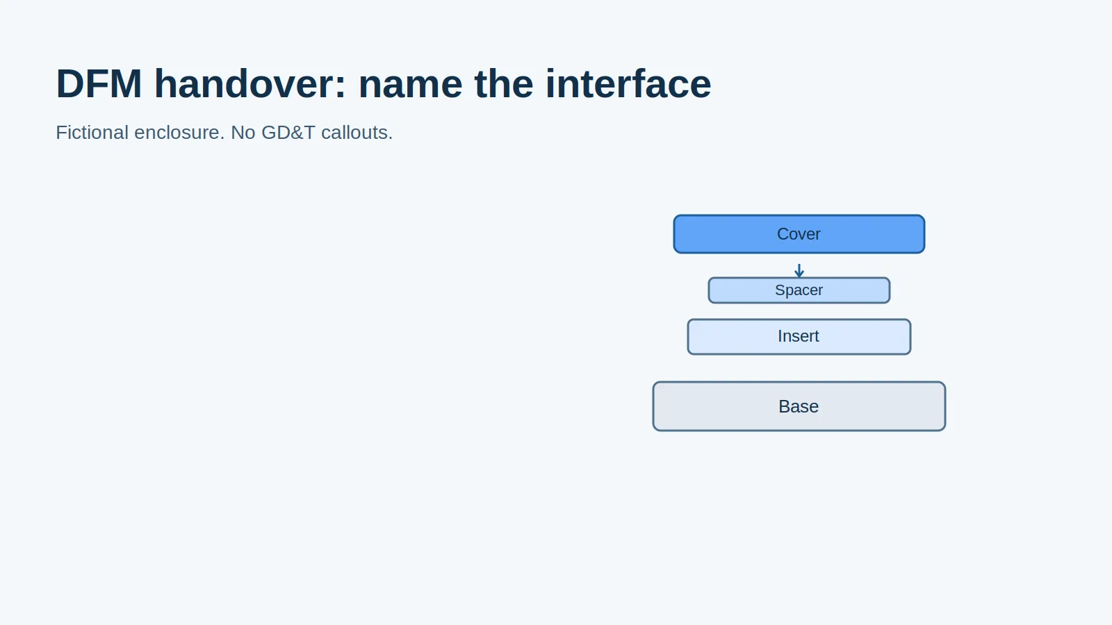
Consider a fictional desk-device enclosure containing a rigid insert, a spacer and a removable cover. The cover must seat without pressing on the insert. Identify the cover’s inner seating surface, the base surface supporting the insert, and the spacer faces that determine the remaining gap.
On an assembly section, mark the direction in which that gap is measured. Then ask a drawing reviewer which surfaces should locate the part during manufacture and inspection. Keep cosmetic surfaces and functional contact surfaces distinguishable: a face that looks convenient in CAD may have little connection to how the assembly actually seats.
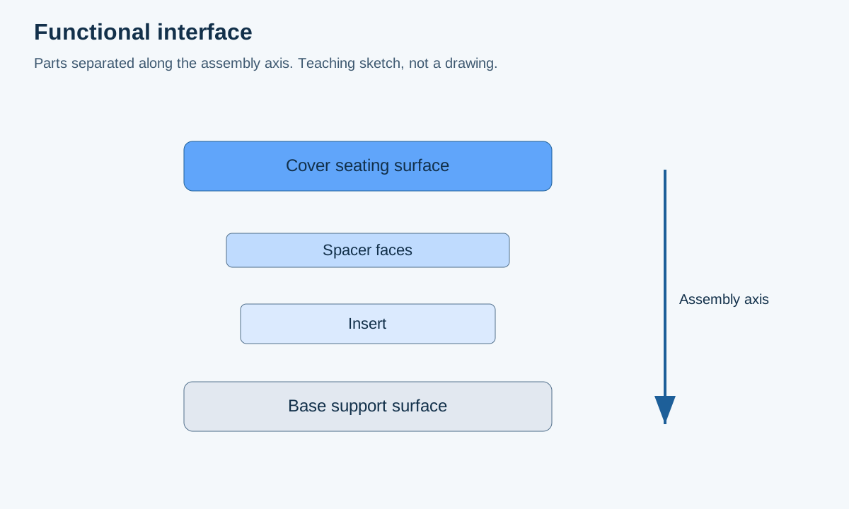
The useful student skill is explaining a requirement in ordinary language before encoding it in a drawing. For example: “The cover must seat on the base without loading the insert; inspect the residual gap along the indicated assembly axis.” A reviewer can question that statement and its measurement method before it becomes a drawing requirement.
Where does GD&T belong?
ASME’s public Y14.5 overview, opened on 19 October 2026, identifies Y14.5-2018 (R2024) and describes GD&T as a common language for requirements on drawings, digital models and related documents, supporting form, fit, function and interchangeability.
That public overview establishes the purpose of the standard; it does not provide the full rules for constructing a particular callout. Our recommendation is to record the agreed drawing standard and edition, explain the functional requirement, and have a competent drawing reviewer check any geometric controls against that standard. This article does not prescribe datum letters, modifiers or feature-control-frame values from material we have not opened. Adding unfamiliar symbols cannot substitute for deciding what the assembly must do.
How do you calculate a tolerance stack before handover?
For this teaching example, assume three rigid, collinear dimensions measured between the contact surfaces already identified. All values below are invented design inputs, not measured parts, supplier capabilities or recommended molding tolerances.
| Symbol | Assumed dimension | Nominal value | Assumed bilateral limit |
|---|---|---|---|
| H | Internal distance from the base support plane to the seated cover’s inner face | 20.00 mm | ±0.15 mm |
| B | Insert height from its support face | 18.80 mm | ±0.10 mm |
| T | Spacer thickness above the insert | 0.60 mm | ±0.05 mm |
The residual clearance is G. In this one-dimensional worst-case model, take the smallest H and subtract the largest B and T. The formula and its substituted line are:
G_nominal = H - B - T
G_nominal = 20.00 - 18.80 - 0.60 = 0.60 mm

G_min = (H - t_H) - (B + t_B) - (T + t_T)
G_min = (20.00 - 0.15) - (18.80 + 0.10) - (0.60 + 0.05)
      = 19.85 - 18.90 - 0.65 = 0.30 mm

G_max = (H + t_H) - (B - t_B) - (T - t_T)
G_max = 20.15 - 18.70 - 0.55 = 0.90 mm
Here, each t is the positive half-width of its dimension’s allowed interval. Equivalently, the clearance half-width is 0.15 + 0.10 + 0.05 = 0.30 mm, giving a nominal 0.60 mm gap with limits of 0.30–0.90 mm. This is interval arithmetic; it uses no statistical distribution assumption.
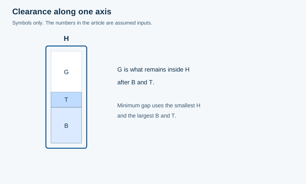
Assume the project brief requires at least 0.20 mm of clearance to avoid contact. The calculated minimum of 0.30 mm clears that assumed requirement by 0.10 mm. The upper gap still needs its own functional review if it permits movement or rattle.
Rule of thumb — hold threshold: If G_min is below the project’s required minimum clearance, hold the tooling release and change the geometry or tolerance allocation. In this example the threshold is 0.20 mm, an assumed project requirement rather than a universal fit allowance.
Passing this calculation does not demonstrate that the proposed molding process can achieve the input limits. Ask the supplier to review them, and reconsider the model if tilt, warpage, compliant pads, temperature change or assembly force affects the gap. Tightening every dimension to rescue a poor nominal design needs a manufacturing justification.
Which DFM question should go to the molder?
Check draft and surface finish together on the same enclosure revision. Protolabs’ plastic injection molding guidelines, opened on 19 October 2026, list 2° of draft for most situations and a 3° minimum for its PM-T1 light texture. These are supplier guidelines with specific conditions, not a guarantee for every resin and tool.
Suppose the fictional cover has a face drawn at 2° and the appearance proposal requests PM-T1 texture there. Flag that face for review: its proposed angle is below the supplier’s stated PM-T1 minimum. Ask whether increasing draft changes the grip, internal space or intended seam, and recalculate the fit if the affected surfaces change.
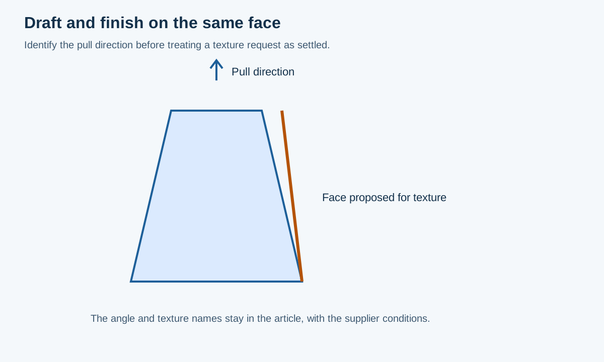
Record the question as a decision: “Cover face F1: proposed PM-T1 texture; revise draft or finish after molder review; tooling held for this item.” Attach an annotated section and name the person closing it. For the broader wall, rib and draft checks, use our injection molding design rules; this worked handover focuses on one conflict rather than repeating that guide.
What makes the handover ready for review?
Bring the supplier a matched model and drawing, the annotated interface section, the clearance calculation with units and assumptions, and the open draft/finish decision. Use the existing handoff checklist to package those records. Label the status accurately: a request for manufacturing feedback is distinct from authorization to cut tooling.
After review, carry any accepted geometry change through the drawing and the calculation. The evidence of mechanical design judgment is that another person can trace a functional requirement through its dimensional budget to a manufacturing decision. This is a student learning exercise based on public sources and a fictional assembly, not a report of a validated production tool.