Machining a prototype that a printer could have answered costs days, and printing one that must behave like production metal gives a false pass. Use 3D printing for early, complex or one-to-ten-piece plastic prototypes; use CNC machining when the test needs production material, tight tolerances or metal, or when you need about 100 or more simple parts.
For a prototype, 3D printing vs CNC machining comes down to what the part must prove and how many you need. Protolabs Network lists CNC tolerances of ±0.025–0.125 mm against ±0.3 mm for SLS and ±0.5 mm for desktop FDM (accessed October 7, 2026), and recommends printing for 1–10 plastic parts and machining from about 100. Printing wins on complex shapes and fast design changes; machining wins on accuracy and true material properties.
This is a comparison based on public sources, not on our own tests: it uses the tolerance and quantity tables of a manufacturing service, a printer maker’s process data and one service’s CNC design rules, all read on October 7, 2026. By the end you will have a decision flow for each prototype stage and a list of design changes each process needs.
Quick specs
| Input or item | Typical value or source | Why it matters |
|---|---|---|
| What the prototype must prove | Your test plan | Appearance and size can be printed; machining gives the block material’s own properties, while molded behaviour still needs molded samples |
| Quantity | Plastic: 1–10 print, 10–100 print or CNC, 100–1,000 CNC, 1,000+ molding (Protolabs Network) | The cheapest process changes with the number of parts |
| Tightest tolerance needed | CNC ±0.025–0.125 mm; SLS ±0.3 mm; FDM ±0.5 mm desktop, ±0.2 mm industrial (Protolabs Network) | A fit test is only meaningful if the process can hold it |
| Material | Production plastic or metal block for CNC; printing resins, filaments and powders (Protolabs) | Machined parts have the material’s own properties; printed parts are usually not uniform in every direction |
| Geometry | Internal channels, lattices, deep undercuts | CNC is limited by tool access and leaves rounded internal corners |
| Thinnest wall | CNC 0.75 mm; SLS 0.7–1.0 mm; FDM 0.8–1.0 mm (Protolabs Network) | Thin ribs and clips may fail on either process below these values |
| How often the design changes | Every few days in early stages | Printing needs no custom tooling or fixtures; a change still means re-slicing and checking orientation and supports |
What is the difference between CNC machining and 3D printing?
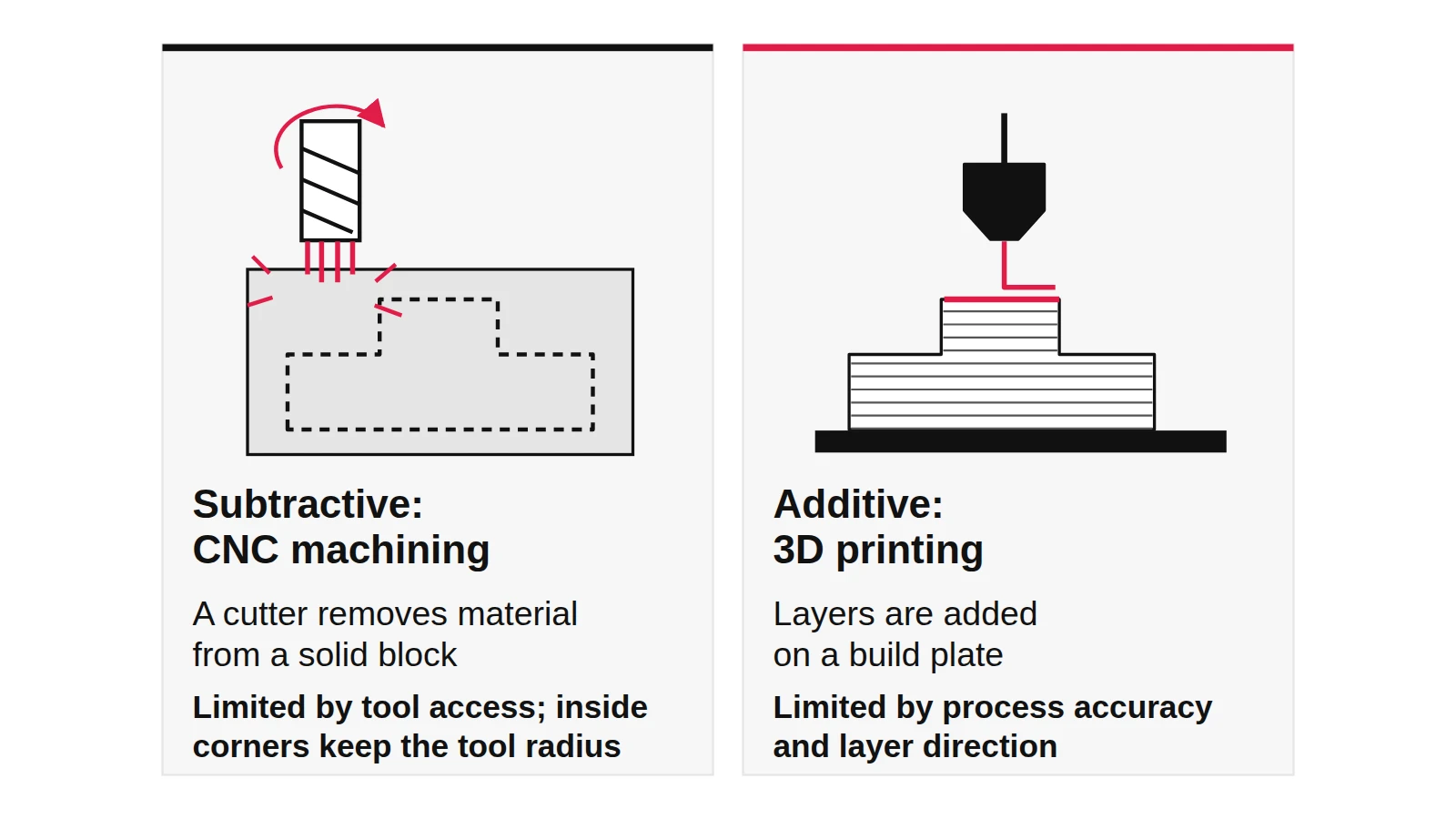
CNC machining is subtractive: a computer-controlled machine cuts a finished shape out of a solid block with rotating tools. 3D printing is additive: it builds the part layer by layer from the CAD file and needs no custom tooling or fixtures. Protolabs Network uses these definitions, and the rest of the differences follow from them.
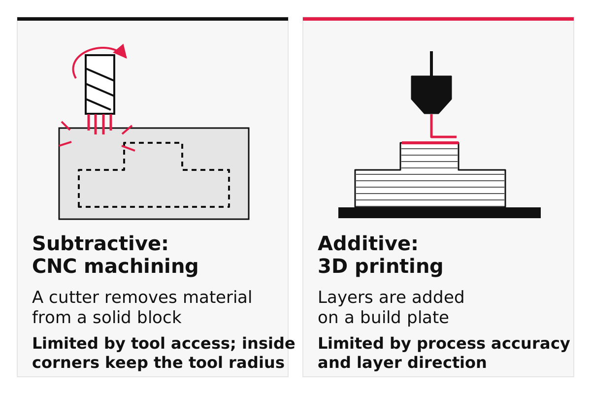
Because a cutter has to reach every surface, CNC is limited by tool access, by how often the part must be re-clamped and by the round shape of the tool, which leaves a radius in every internal corner. Because a printer deposits or fuses material, it can make internal channels and lattices, but its accuracy, surface and strength depend on the process and on how the part is oriented.
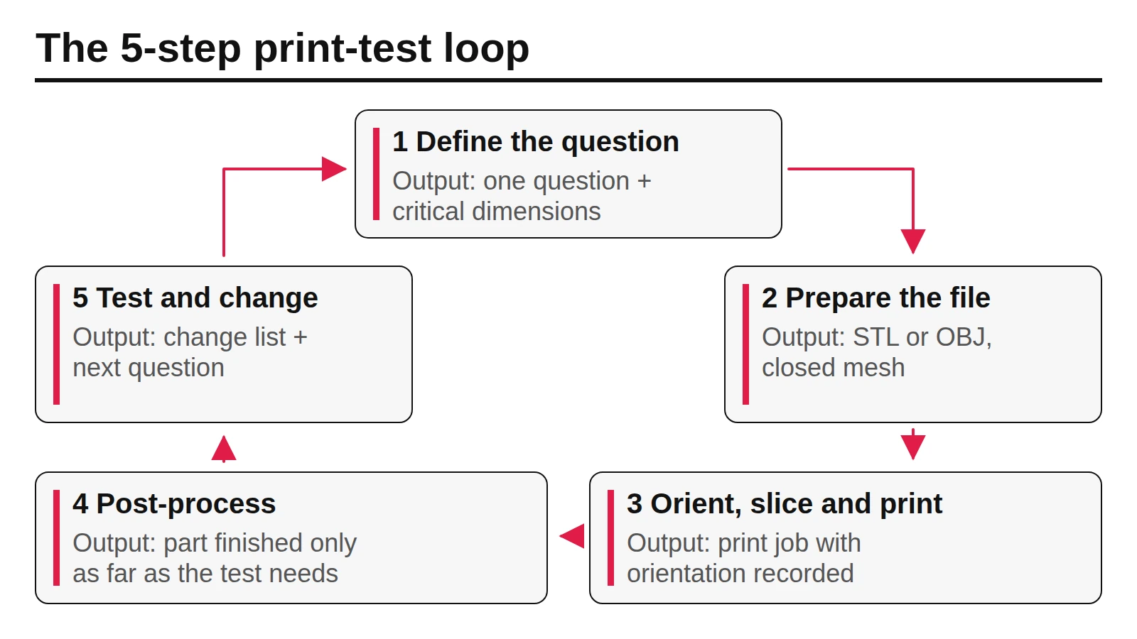
The workflows differ too. Protolabs Network describes CNC as labour-intensive: a skilled operator chooses tools, programs spindle speeds and cutting paths, and sets up workholding. A printer, once the file is prepared and oriented, builds the part with little operator input, although support removal, cleaning and curing can take hours. For the printing side in detail, see the five-step print-test loop.
Takeaway: Subtractive means tool access and setup decide what is possible; additive means orientation and process decide how good the part is.
3D printing vs CNC machining side by side
On the same eight factors, CNC leads on tolerance, material properties and finish on simple shapes, while 3D printing leads on geometric freedom, setup and the cost of the first few parts. The table compares them for plastic prototypes; values are typical figures published by the named companies, not guarantees.
| Factor | 3D printing (FDM, SLA, SLS) | CNC machining |
|---|---|---|
| Tolerance (Protolabs Network) | FDM ±0.5 mm desktop, ±0.2 mm industrial; SLS ±0.3 mm; SLA to be confirmed with your printer or service | ±0.025–0.125 mm depending on the tolerance level specified |
| Thinnest wall (Protolabs Network) | FDM 0.8–1.0 mm; SLS 0.7–1.0 mm | 0.75 mm |
| Material properties | Typically not fully uniform in all directions (Protolabs); FDM is weakest between layers, while SLA and SLS are closer to uniform, according to Formlabs | The block material’s own properties, uniform in all directions (Protolabs) |
| Plastics available | Printing plastics such as ABS-like and PC-like resins, nylon and polypropylene; flexible TPU prints more easily than it machines (Protolabs) | Production plastics such as ABS, acetal, PC, nylon and PEEK (Protolabs) |
| Geometry | Few limits; SLS needs no supports, so hollow parts and internal channels work | Limited by tool reach; internal corners keep the tool radius |
| Setup before the first part | File preparation and orientation | Tool selection, programming and fixturing |
| Surface straight off the machine | Layer lines or a grainy texture, depending on process | Visible tool marks, edges broken (Protolabs) |
| Changing the design | Re-slice and print | New toolpaths, sometimes new fixtures |
Read the tolerance row with care: it compares a service’s typical values, and a desktop FDM printer in a makerspace may do worse than an industrial one. If one dimension is critical, Protolabs Network suggests printing that area oversize and machining it afterwards.
Takeaway: Compare the two processes on the factor your test depends on; there is no overall winner.
Which process fits each prototype stage?
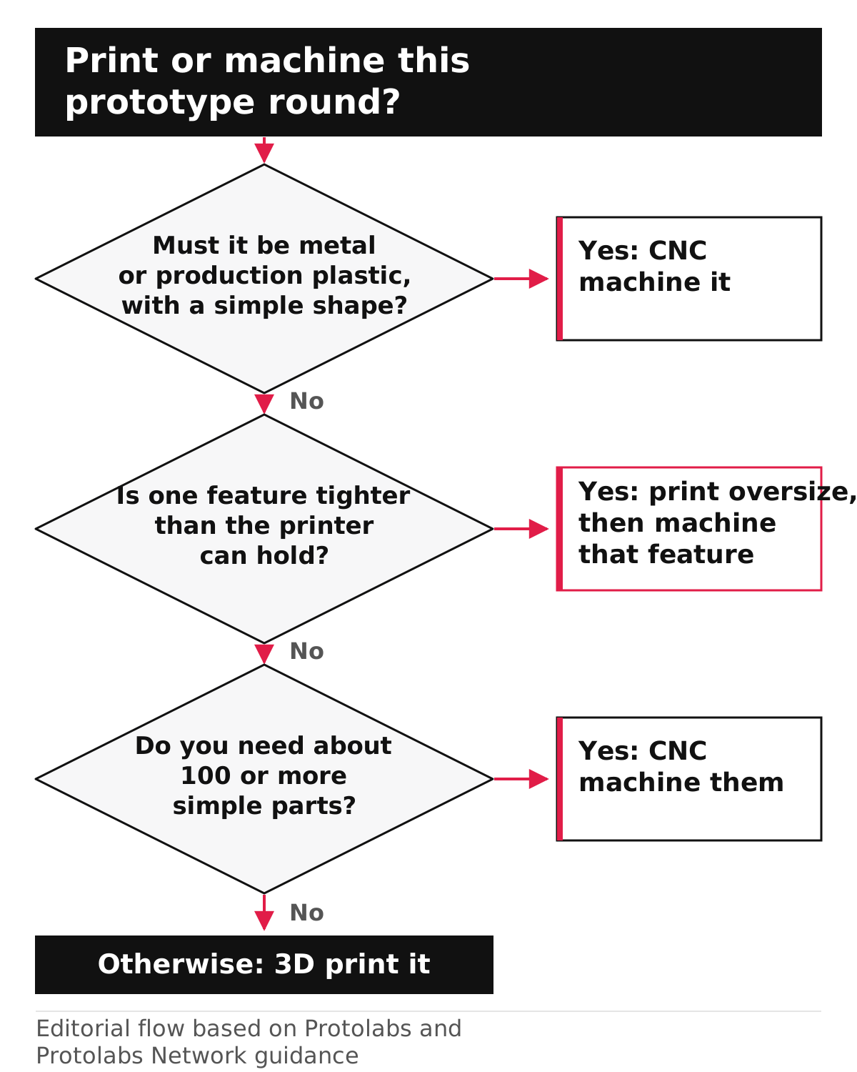
Print the early rounds, machine the rounds where production material or tolerance decides the result, and combine the two when one feature is critical. The flow below turns that into four questions you can answer before every order; it is our editorial guide built on the published recommendations above.
| Stage | Typical question | Usual choice | Why |
|---|---|---|---|
| Appearance and size models | Does it look and feel right? | 3D printing | Fast, no custom tooling or fixtures |
| Ergonomics and user tests | Can people use it comfortably? | 3D printing, SLA for small details | Several variants in one batch |
| Fit and function in plastic | Do clips and hinges work? | SLS or industrial FDM; CNC if the clip must be checked in a specified plastic | Printing is quick; machined parts have the block material’s own properties |
| Load, heat or wear tests | Will it survive real use? | CNC in the specified material, then the final process | Production-grade material with uniform properties (Protolabs); the final process still needs confirming |
| Small batch for testers | Can 20 to 100 people use it? | Printing or CNC, depending on shape | Protolabs Network lists 10–100 plastic parts as printing, with CNC worth considering |
| Pre-production | Is the design ready for molding? | CNC, then molded samples | Machined parts use production-grade plastics, but only molded samples confirm molded behaviour |
The rapid prototyping guide explains how to set the fidelity of each stage. Ergonomic questions stay printable even late in a project: in our example, the size and feel of an actuator like the large one Aptar describes for its L’Occitane hand care pump could be judged on SLA prints; Aptar has not said how it tested its own. Record which process you chose for each round and why; that reasoning is what reviewers look for in a design portfolio. Some functional questions only appear late; a pump maker, for example, has to show that its dispenser survives shipping. Aptar says its Novus Advance pump passed its in-house ISTA-6 testing, and notes that results may vary with container shape, size and formula.
Common mistake: Ordering a machined prototype because it looks more professional when the question is only about size or appearance. For one-off models, a print usually answers that question sooner and, by Protolabs Network’s guidance, typically for less below 10 units.
Takeaway: Decide by the question each round must answer, not by which part looks more finished.
How does cost change with quantity?
CNC carries setup work for every new design, programming and fixturing, which is then shared across the parts; a printer has no tooling to share out, although nesting several parts in one build and batching post-processing can lower its cost per part, as Formlabs describes for SLS. That is why printing tends to win for one-offs and machining as numbers grow. Protolabs Network says printing is typically cheaper than CNC below 10 units, and Protolabs suggests machining for parts above about 100 with straightforward shapes.
| Number of plastic parts | Protolabs Network recommendation | What drives the choice |
|---|---|---|
| 1–10 | 3D printing | No custom tooling or fixtures to pay for |
| 10–100 | 3D printing, consider CNC | Shape complexity decides |
| 100–1,000 | CNC machining, consider injection molding | Setup is shared across many parts |
| 1,000+ | Injection molding | Tooling cost is shared across very many parts |
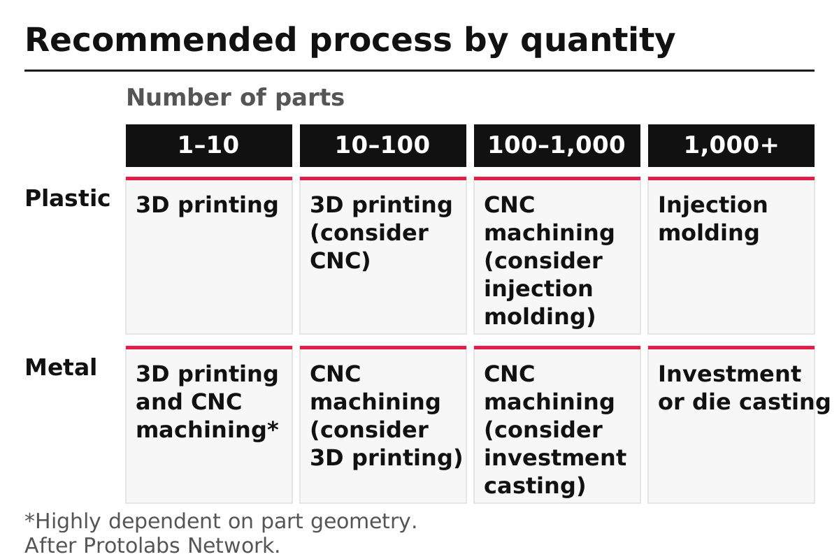
For metal parts the bands shift: Protolabs Network lists both printing and CNC for 1–10 metal parts depending on geometry, CNC from 10 to 1,000, and investment or die casting beyond that. Protolabs adds that cost also depends on lead time, the material chosen and geometric complexity, and we do not quote prices because they vary by service and date.
At the top of the plastic range, the design has to change before a tool is made. The injection molding design rules cover what a molded part needs that a printed or machined one does not, such as draft and even wall thickness.
Takeaway: Count your parts before choosing; the crossover depends on how complex the shape is.
Designing an enclosure part for each process
The same housing needs different details on each process: on FDM, clips must be oriented so the bending load does not pull the layers apart, and machining needs internal corner radii and features a cutter can reach. Protolabs Network’s enclosure example lists snap fits, living hinges and interlocking joints as typical housing features and notes they can be prototyped by printing or machining. The table uses an illustrative kiosk control-panel housing.
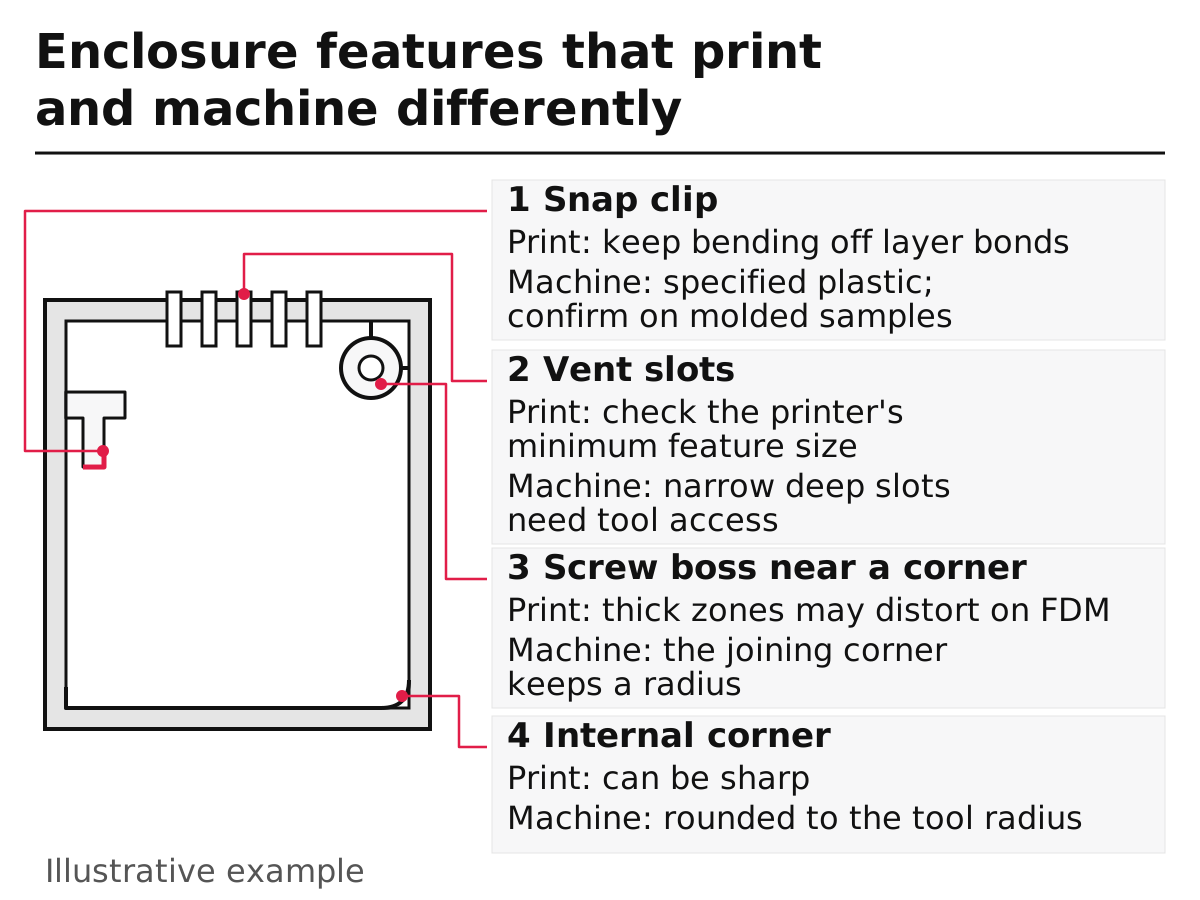
| Feature | If you 3D print it | If you machine it |
|---|---|---|
| Snap clip | On FDM, check that bending does not load the layer bonds; SLA and SLS are closer to uniform (Formlabs) | Machine from the specified plastic to check material behaviour; confirm on molded samples |
| Vent slots | Check slot and wall widths against your printer’s minimum features; FDM handles fine features less well than SLA or SLS (Formlabs) | Narrow, deep slots need a small cutter that may not reach; check tool access |
| Screw boss near a thick corner | Thick regions print, but take longer and may distort on FDM | Machinable; the internal corner where it meets the wall keeps a radius |
| Internal corners | Can be sharp if the process resolves them | Protolabs rounds sharp inside corners to the smallest tool radius |
| Thin features | FDM about 0.8 mm minimum wall (Formlabs) | Protolabs recommends features thicker than 0.020 in (0.51 mm) and a nominal thickness above 0.040 in (1.02 mm) |
| Engraved text | Small text may blur on FDM | Protolabs gives a minimum text width of 0.018 in (0.457 mm) on plastics |
Protolabs Network’s enclosure example also lists typical lead times on its platform: 1–3 days for FDM, under a week for SLS and 1–2 weeks for CNC. Treat these as one service’s figures; the other prototyping guides explain how to plan rounds around them. If the housing is heading for molding, check walls and bosses against the rib and boss guidance before the machined round, so the prototype resembles the final part. Our CNC machining articles collect the related topics.
Common mistake: Designing sharp inside corners for a machined part. The cutter is round, so the corner comes back with a radius and a mating part may not sit flush.
Takeaway: Change the model for the process you choose; a file designed for printing rarely machines well unchanged.
What about metal 3D printing vs CNC machining?
For metal parts with simple shapes, CNC machining is usually the better prototype: Protolabs Network recommends it for strength, heat performance and tight tolerances, while metal printing suits complex, organic or lattice shapes and hard-to-machine alloys. Its tables give metal powder bed fusion (SLM/DMLS) about ±0.100 mm, a 0.40 mm minimum wall and a maximum part size of 230 × 150 × 150 mm, against CNC’s ±0.025–0.125 mm.
| Factor | Metal printing (SLM/DMLS) | CNC machining |
|---|---|---|
| Tolerance | About ±0.100 mm | ±0.025–0.125 mm |
| Minimum wall | 0.40 mm | 0.75 mm |
| Maximum size listed | 230 × 150 × 150 mm | Milling up to 2,000 × 800 × 1,000 mm |
| Best for | Complex, organic, lightweight or lattice shapes; alloys such as Inconel | Simple shapes, high loads, tight tolerances |
Protolabs Network suggests a hybrid route for critical metal parts: print the complex core, then machine mounting holes and sealing surfaces to tolerance. For a student project, metal printing is rarely the first prototype; it becomes worth evaluating when the shape is hard to machine, the alloy is hard to cut or weight matters, the cases Protolabs Network lists.
Takeaway: Machine simple metal parts; evaluate printing for complex shapes, hard-to-machine alloys or lightweight structures.
When this does not apply
The comparison covers prototypes in plastic and simple metal parts, ordered from common services or made on common equipment. It does not hold in these cases:
- Other processes. Vacuum casting, sheet metal and laser cutting can beat both for some prototypes; they are not compared here.
- Your own machines. A makerspace printer or router may be less accurate than a service’s industrial equipment. Measure a test part before trusting the tables.
- Regulated parts. Medical, food-contact and safety-critical uses are outside this comparison; check the requirements that apply to the product’s use.
- Costs and lead times. We give no prices, and the lead times quoted are one service’s typical figures. Get quotes for your own part.
- Production decisions. A prototype process choice says little about the best production process; molding and casting appear at higher quantities. The ALPLA foam pump reading looks at a pump that ALPLA says is made entirely of polypropylene, a design built around one molding material.
Takeaway: Use the tables as a starting point and confirm tolerance, cost and lead time on your own part.
How this page was put together
We compiled this page on October 7, 2026 from public sources: Protolabs Network’s comparison of 3D printing and CNC machining (tolerances, wall thicknesses, quantity table, enclosure and metal examples), a Protolabs article from August 3, 2023 (definitions, material and quantity guidance), Protolabs’ CNC milling design guidelines (feature sizes and corner radii) and Formlabs’ guide to FDM, SLA and SLS (minimum wall and layer behaviour). Protolabs and Protolabs Network are one company and sell both processes; Formlabs makes printers. We present their figures as their statements. The decision flow, stage table and kiosk housing example are our editorial guidance, not test results. The pump examples come from Aptar’s and ALPLA’s own announcements.
Takeaway: Before ordering, write down the question, quantity and critical tolerance for the round, then check them against the chosen service’s published limits.
Related reading:
- Rapid prototyping with 3D printing — Run the print-test loop and choose between FDM, SLA and SLS.
- Injection molding design rules — Prepare a prototype design for the jump to molding.
- Industrial design portfolio guide — Show which process you chose for each round and why.