Design for Manufacturing and Assembly (DFMA) combines Design for Assembly (DFA), which optimizes how parts go together, with Design for Manufacturing (DFM), which optimizes how each part is made, before anything is committed to tooling. 80% of manufacturing cost is locked in during design, before a supplier ever sees the drawing. A design change after tooling can cost 10–100× more than the same change during concept.
Understanding what is design for manufacturing and assembly requires separating single-part geometric checks from system-level architecture within our DFM and hardware engineering resources. While stage-gate entrance and exit deliverables across prototyping milestones live in our companion guide on what is design for manufacturing (DFM) stage-gate checkpoints, this guide examines the engineering judgments that DFMA adds beyond individual part manufacturability.
| Review dimension | Single-part DFM or standardization approach | System-level DFMA engineering judgment | Consequence of skipping DFMA |
|---|---|---|---|
| Application sequence | DFMA is applied in sequence with DFA first to eliminate unnecessary parts and reduce assembly complexity, followed by DFM to optimize each remaining part | ||
| Bill of Materials (BOM) scope | Part-level tools usually optimize within a fixed BOM | DFMA is built to interrogate the BOM itself before any part is detailed | |
| Consolidated part evaluation | Part-level DFM checkers evaluate parts one at a time and may flag a consolidated part | DFMA measures the whole product | Missing the 12 fasteners, 3 suppliers, and extra assembly station required by the alternative |
| Cover plate fastening | A standardized cover plate using ten identical screws still leaves ten parts to handle | A consolidated DFMA plate integrates snap-fit features with no loose fasteners | |
| Typical portfolio outcome | Across Boothroyd Dewhurst DFMA applications, typical outcome ranges are 20–50% part-count reduction, 10–30% assembly-time reduction, and 15–40% total product-cost reduction |
What Is Design for Manufacturing and Assembly (DFMA)—and Why Does Single-Part DFM Miss Assembly Cost?
Geoffrey Boothroyd and Peter Dewhurst founded Boothroyd Dewhurst, Inc. in 1983 and received the U.S. National Medal of Technology and Innovation in 1991 for the concept, development, and commercialization of DFMA. Across design and manufacturing workflows, DFMA combines DFA, which optimizes how parts go together, with DFM, which optimizes how each part is made, before anything is committed to tooling.
Why DFA Comes Before DFM in Sequence
DFMA is applied in sequence with DFA first to eliminate unnecessary parts and reduce assembly complexity, followed by DFM to optimize each remaining part. Part-level tools usually optimize within a fixed BOM, whereas DFMA is built to interrogate the BOM itself before any part is detailed.
80% of manufacturing cost is locked in during design, before a supplier ever sees the drawing. Once tooling is cut, a design change after tooling can cost 10–100× more than the same change during concept.
The Single-Part DFM Trap: One Consolidated Casting vs. Four Stamped Parts
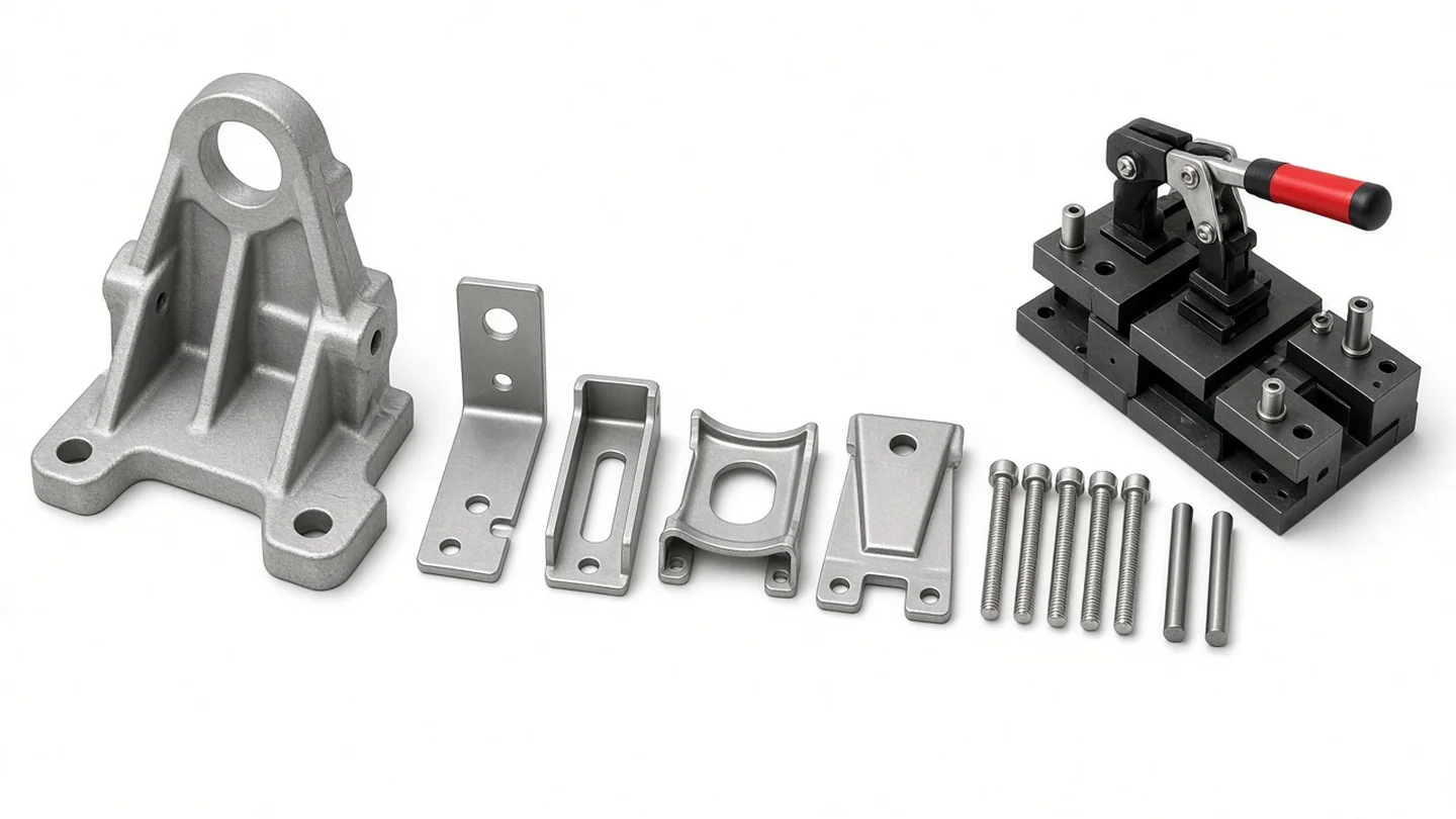
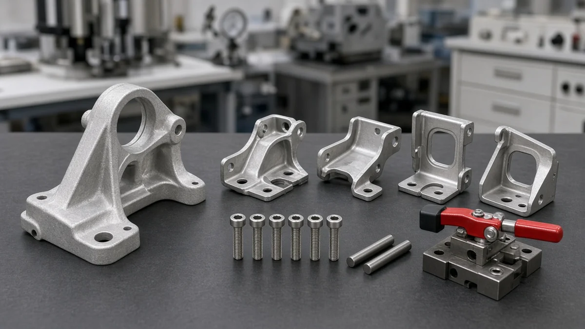
Part-level DFM checkers evaluate parts one at a time and may flag a consolidated part while missing the 12 fasteners, 3 suppliers, and extra assembly station required by the alternative. In Boothroyd Dewhurst’s bracket example, breaking an integrated die-cast bracket into simpler tooling components created four stamped parts, six fasteners, two alignment pins, and a welding fixture.
Why Fastener Standardization Is Not DFMA Consolidation
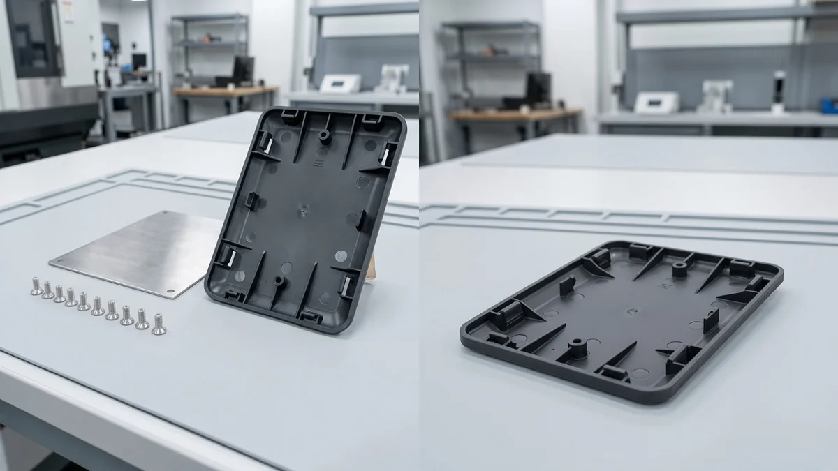
Hardware teams frequently confuse component standardization with DFMA architecture simplification. Standardization is not DFMA: a standardized cover plate using ten identical screws still leaves ten parts to handle, whereas a consolidated DFMA plate integrates snap-fit features with no loose fasteners.
Takeaway: Interrogate the Bill of Materials with DFA before running part-level DFM checks so you do not split consolidated functional structures into multi-part assemblies held together by loose fasteners and fixtures.
Boothroyd-Dewhurst Theoretical Minimum Part Count: The Three Criteria and DFA Index
To determine whether each part in an assembly has an engineering justification to exist separately, Boothroyd, Dewhurst, and Knight evaluate every component added to the base part against three theoretical minimum-part-count criteria.
The Three Theoretical Minimum-Part-Count Criteria
- First theoretical minimum part count criterion: during normal operation of the product, the part moves relative to all other parts already assembled (small motions via elastic hinges do not qualify).
- Second theoretical minimum part count criterion: the part must be of a different material than, or must be isolated from, all other parts assembled (for insulation, electrical isolation, vibration damping, etc.).
- Third theoretical minimum part count criterion: the part must be separate from all other assembled parts because otherwise the assembly of parts meeting one of the preceding criteria would be prevented.
A part that answers no to all three minimum-part-count questions is a candidate to combine or eliminate. Separate fasteners do not generally meet any of the three minimum-part-count criteria and should always be considered for elimination.
| Minimum-part-count evaluation item | Engineering criterion or boundary | Design disposition when evaluated |
|---|---|---|
| Criterion one: relative motion | During normal operation of the product, the part moves relative to all other parts already assembled (small motions via elastic hinges do not qualify) | |
| Criterion two: material or isolation | The part must be of a different material than, or must be isolated from, all other parts assembled (for insulation, electrical isolation, vibration damping, etc.) | |
| Criterion three: assembly access | The part must be separate from all other assembled parts because otherwise the assembly of parts meeting one of the preceding criteria would be prevented | |
| All three criteria answered no | A part that answers no to all three minimum-part-count questions is a candidate to combine or eliminate | |
| Separate screws, washers, and clips | Separate fasteners do not generally meet any of the three minimum-part-count criteria and should always be considered for elimination |
Calculating the Boothroyd-Dewhurst DFA Index
The DFA index is obtained by dividing the theoretical minimum assembly time by the actual assembly time. In the DFA index equation, the basic assembly time ta is the average time for one part that presents no handling, insertion, or fastening difficulties, which is about 3 s.
DFA Index Equation:
  E_ma = (N_min * t_a) / t_ma

Where:
  N_min = theoretical minimum number of parts
  t_a   = basic assembly time for one easy-to-handle, easy-to-insert part
  t_ma  = estimated total actual manual assembly time
In Boothroyd, Dewhurst & Knight’s controller assembly baseline, the original design has 19 parts and subassemblies, six additional operations, a total assembly time of 206.43 s, an assembly cost of $1.72 at $30/hr, a theoretical minimum of five parts, and a DFA index of 7% (5 x 3/206.43 = 0.07).
Production Volume and Serviceability Boundaries: When Not to Consolidate Parts
Passing the theoretical minimum-part-count audit does not mean every candidate part should be merged without checking production economics and field maintenance:
- Low production volume cannot always amortize consolidated tooling: a die-cast part replacing four stampings saves money at 100,000 units per year, whereas at 2,000 units per year the tooling cost never pays back.
- If a high-wear component is consolidated with a high-value one, the entire assembly has to be replaced when the wear part fails, which is a strike against consolidation for serviceable products.
A part that answers no to all three minimum-part-count questions is a candidate to combine or eliminate.
Takeaway: Audit every part in the BOM against the three theoretical minimum-part-count criteria first, then verify tooling payback volume and wear-part serviceability before merging geometry.
Z-Axis Top-Down Pyramid Assembly, Rotational Symmetry, and Self-Locating Rules
Once non-essential parts are removed from the BOM, DFMA optimizes how the surviving components are oriented, aligned, and inserted on the workbench.
Unidirectional Z-Axis Pyramid Assembly and Eliminating Fixture Flips
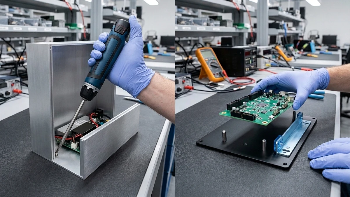
Insertion guideline 3 directs engineers to use pyramid assembly providing progressive assembly about one axis of reference, and in general it is best to assemble from above. Stack parts top-down along a single axis to avoid flips, rotations, and awkward access mid-build. Insertion guideline 7 directs engineers to avoid the need to reposition the partially completed assembly in the fixture.
Building an assembly on a flat base part provides relatively unrestricted access compared with installing screws inside a box-shaped base part with restricted access.
Alpha and Beta Rotational Symmetry vs. Obvious Asymmetry (Poka-Yoke)
Every part picked from a feeder or bin must be oriented along two rotational axes before insertion:
- Alpha Rotational Symmetry: Alpha symmetry is the rotational symmetry of a part about an axis perpendicular to its axis of insertion; end-to-end orientation is necessary when alpha equals 360 degrees, otherwise alpha equals 180 degrees.
- Beta Rotational Symmetry: Beta symmetry is the rotational symmetry of a part about its axis of insertion, defined as the smallest angle through which the part can be rotated and repeat its orientation (zero for a cylinder in a circular hole).
- Mating Hole Geometry Impact: A square prism inserted into a square hole repeats orientation every 90° (90° beta symmetry), whereas inserting the square prism into a circular hole gives 180° alpha symmetry and 0° beta symmetry.
Make parts either fully symmetric (where orientation does not matter) or obviously asymmetric (where only one way fits) to cut handling time and errors. For ease of part handling in bulk storage, provide features that prevent jamming of parts that tend to nest or stack and avoid features that allow tangling.
Self-Locating Features, Peg Chamfer Rules, and Kinematic Constraint
To eliminate manual holding, searching, and adjustment during insertion, apply four geometric locating rules:
- Use self-locating tabs, slots, and grooves so parts drop into one position without separate alignment or holding steps.
- A chamfer on the peg is more effective in reducing manual insertion time than the same chamfer on the hole, and the maximum effective chamfer width for both peg and hole is approximately 0.1-D.
- Locating a square block in a plane with six point constraints overconstrains the part and requires adjustment, whereas kinematic design principles require only three point constraints together with closing forces.
- In the Engineering LibreTexts generalized manual assembly framework, simple straight-line insertion with self-aligning features takes 1.0 - 2.0 seconds, whereas difficult multi-direction alignment takes 3.5 - 5.0 seconds and obstructed access takes 4.0 - 6.0 seconds.
When establishing datum surfaces and worst-case clearance budgets across these self-locating interfaces, pair your kinematic locating layout with our worked guide on mechanical design engineer DFM handover skills and tolerance stacks.
| Assembly orientation or locating factor | High-penalty design condition | Low-penalty DFMA design rule |
|---|---|---|
| Insertion axis & fixture flips | Stack parts top-down along a single axis to avoid flips, rotations, and awkward access mid-build | |
| Base chassis architecture | Restricted access within a box-shaped base part | Building an assembly on a flat base part provides relatively unrestricted access compared with installing screws inside a box-shaped base part with restricted access |
| Part rotational symmetry | Make parts either fully symmetric (where orientation does not matter) or obviously asymmetric (where only one way fits) to cut handling time and errors | |
| Square prism mating geometry | A square prism inserted into a square hole repeats orientation every 90° (90° beta symmetry) | Inserting the square prism into a circular hole gives 180° alpha symmetry and 0° beta symmetry |
| Peg-in-hole lead-in chamfer | Unchamfered mating edges or chamfers placed only on the hole | A chamfer on the peg is more effective in reducing manual insertion time than the same chamfer on the hole, and the maximum effective chamfer width for both peg and hole is approximately 0.1-D |
| Planar locating constraints | Locating a square block in a plane with six point constraints overconstrains the part and requires adjustment | Kinematic design principles require only three point constraints together with closing forces |
| Alignment & access insertion time | Difficult multi-direction alignment takes 3.5 - 5.0 seconds and obstructed access takes 4.0 - 6.0 seconds | In the Engineering LibreTexts generalized manual assembly framework, simple straight-line insertion with self-aligning features takes 1.0 - 2.0 seconds |
Takeaway: Build assemblies top-down along a single Z-axis on an open base part, design parts to be either symmetric or unmistakably keyed, use 0.1-D peg chamfers, and locate planar interfaces with three kinematic constraints rather than overconstrained six-point stops.
Fastener Consolidation Hierarchy and Step-Two DFM Checks on Surviving Parts
Manual and Automatic Fastening Cost Hierarchy
When common mechanical fasteners are used, their relative sequence in order of increasing manual assembly cost is: (a) Snap fitting, (b) Plastic bending, (c) Riveting, and (d) Screw fastening.
In the Engineering LibreTexts generalized manual assembly framework, insertion requiring multiple fasteners (screws, clips, or additional securing) takes an estimated 5.0 - 8.0 seconds per fastener, compared with 1.5 - 2.5 seconds for snap-fit or self-locking features. In Engineering LibreTexts worked example, assembling a small symmetric plastic cover (0.3 kg) with a snap-fit mechanism takes 1.5 seconds for handling plus 1.5 seconds for snap-fit insertion, totaling 3.0 seconds per operation.
In automatic assembly, each small part such as a fastener, clip, or washer requires a feeding and orienting device, a workhead, at least one extra work carrier, a transfer device, and an increase in size of the basic machine structure. When springs are unavoidable in an assembly, leaf springs can be placed and loaded, extension springs require force to be loaded, and compression springs have to be held down for assembly.
Step-Two DFM Verification on Surviving Molded, Sheet-Metal, and Machined Parts
After DFA consolidates parts and eliminates loose screws, the second half of DFMA verifies that each surviving component is economical to fabricate in its chosen process:
- Injection-Molded Plastic Components: In Boothroyd Dewhurst’s injection molding DFM checklist for surviving parts, check for uniform wall thickness (±10% variation target), draft angles ≥ 1° on all vertical surfaces, and ribs ≤ 60% of adjacent wall thickness. (For full polymer-by-polymer wall, rib, boss, and texture-draft tables, see our reference on injection moulding design guidelines for wall thickness, draft angles, and ribs.)
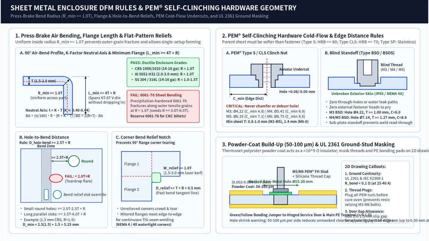
- Sheet-Metal Stamped and Formed Components: In Boothroyd Dewhurst’s sheet metal DFM checklist, verify that bend radii are ≥ material thickness, hole-to-edge spacing is ≥ 2× material thickness, and hole-to-bend spacing is ≥ 2× thickness + bend radius.
- CNC-Milled Machined Components: In Boothroyd Dewhurst’s milled aluminum bracket DFM micro-case, removing small-tool paths (increasing internal corner radius from 1 mm to 3 mm) and secondary ops commonly yields cycle time reductions of ~12–18% and piece-part cost reductions of ~9–14%.
- Engineering Drawing Boundary for Surviving Parts: MIT OpenCourseWare D-Lab instructs engineers to produce technical drawings only for critical custom-made components and not for screws, nuts, or off-the-shelf parts.
Takeaway: Replace screw fastening with snap fitting or plastic bending wherever disassembly conditions allow, verify wall, bend, and corner-radius DFM rules on each surviving custom part, and issue detail drawings only for custom-made components.
Documented DFMA Redesign Benchmarks and Worked Case Studies
Across Boothroyd Dewhurst DFMA applications, typical outcome ranges are 20–50% part-count reduction, 10–30% assembly-time reduction, and 15–40% total product-cost reduction.
Motor-Drive Class and Controller Subassembly Redesigns
In Boothroyd Dewhurst’s representative ranges for motor-drive class assemblies, total parts drop from 25–35 before DFMA to 8–12 after DFMA (60–75% reduction), and separate fasteners drop from 10–15 to 2–4 (70–85% reduction). In Boothroyd Dewhurst’s motor-drive class assembly benchmark, assembly time drops from 180–240 sec to 60–90 sec (60–70% reduction), assembly operations drop from 20–25 to 8–10 (60–65% reduction), and the DFA design-efficiency index rises from 5–10% to 55–65%.
In the controller assembly analysis, combining the plastic cover with the metal frame eliminates the cover assembly operation, three screws, and a reorientation operation, saving 52.05 s (25% of total assembly time). In the conceptual redesign of the controller assembly, all proposed design changes save 133.8 s of assembly time (65% of the total), reducing total assembly time to 77.93 s and increasing assembly efficiency to 19%.
Industrial, Medical, Commercial, and Consumer Hardware Case Comparisons
- U.S. DOE piston subassembly: In the U.S. DOE piston subassembly example, employing the Boothroyd and Dewhurst DFA methodology reduces assembly time from 37 seconds to 15 seconds and increases the DFA index from 32 to 79.
- Two-Speed Reciprocating Power Saw: In Boothroyd, Dewhurst & Knight’s two-speed reciprocating power saw analysis, the initial design had 41 parts and an estimated assembly time of 6.37min, while the redesign had 29 parts (29% reduction) and an estimated assembly time of 2.58min (59% reduction).
- IDEXX Catalyst Dx Maintenance Access Door: In the IDEXX Catalyst Dx Maintenance Access Door DFA redesign, consolidating a 43-part main panel into a single molded piece with snap and slip fits reduced part count from 183 to 31 (83% reduction), fasteners from 63 to 0 (100% eliminated), and assembly time from 45 to 11 minutes (75% reduction). In the IDEXX Catalyst Dx Maintenance Access Door DFA redesign, assembly cost fell from $622 to $384 (38% reduction), alignment time fell from 11 min to 3 min (73% reduction), weight fell from 5.8 lbs to 3.5 lbs (40% reduction), and the DFA Index rose from 3.8 to 35.8 (842% improvement).
- NCR Voyix 2760 POS Terminal: In the NCR Voyix 2760 POS terminal DFMA redesign, NCR Voyix reduced part count by 85%, reduced assembly time by 75%, reduced suppliers by 65%, and reduced manufacturing labor costs by 44% ($1.1 million savings). In the NCR Voyix POS terminal redesign, eliminating just one screw would have saved $12,500 over the lifetime of production, and the screwless snap-fit design allowed all 15 pieces to be assembled in less than two minutes.
- Computer Mouse Redesign: In Boothroyd Dewhurst’s computer mouse DFMA redesign, unique mechanical parts fell from 31 to 16 (48% fewer parts), electrical parts fell from 30 to 28, assembly time fell 65% from 17 minutes to six minutes per unit, assembly operations fell from 83 to 56, ten screws and ten to eleven adjustments were eliminated, and material costs fell 40%.
- CNH Industrial Tractor Cooling Package: At CNH Industrial, applying DFMA during the concept phase of a tractor cooling package eliminated 58 parts through snap-fits, integrated features, and welded sub-assemblies, dropping the part count from 352 to 294 and reducing assembly time by 18 percent.
| Documented assembly or case study | Part and fastener consolidation outcome | Assembly time, cost, or DFA Index impact |
|---|---|---|
| Motor-drive class benchmark (parts & fasteners) | Total parts drop from 25–35 before DFMA to 8–12 after DFMA (60–75% reduction), and separate fasteners drop from 10–15 to 2–4 (70–85% reduction) | |
| Motor-drive class benchmark (time & DFA index) | Assembly operations drop from 20–25 to 8–10 (60–65% reduction) | Assembly time drops from 180–240 sec to 60–90 sec (60–70% reduction), and the DFA design-efficiency index rises from 5–10% to 55–65% |
| Controller assembly (cover & frame consolidation) | Combining the plastic cover with the metal frame eliminates the cover assembly operation, three screws, and a reorientation operation | Saves 52.05 s (25% of total assembly time) |
| Controller assembly (full conceptual redesign) | Applies all proposed DFA consolidation and handling improvements across the controller assembly | Saves 133.8 s of assembly time (65% of the total), reducing total assembly time to 77.93 s and increasing assembly efficiency to 19% |
| U.S. DOE piston subassembly | Applies Boothroyd and Dewhurst DFA consolidation to piston subassembly | Reduces assembly time from 37 seconds to 15 seconds and increases the DFA index from 32 to 79 |
| Two-speed reciprocating power saw | Initial design had 41 parts while the redesign had 29 parts (29% reduction) | Estimated assembly time dropped from 6.37min to 2.58min (59% reduction) |
| IDEXX Catalyst Dx door (parts & fasteners) | Consolidating a 43-part main panel into a single molded piece with snap and slip fits reduced part count from 183 to 31 (83% reduction) and fasteners from 63 to 0 (100% eliminated) | Assembly time fell from 45 to 11 minutes (75% reduction) |
| IDEXX Catalyst Dx door (cost & DFA Index) | Weight fell from 5.8 lbs to 3.5 lbs (40% reduction) and alignment time fell from 11 min to 3 min (73% reduction) | Assembly cost fell from $622 to $384 (38% reduction) and the DFA Index rose from 3.8 to 35.8 (842% improvement) |
| NCR Voyix 2760 POS terminal | Reduced part count by 85% and reduced suppliers by 65% | Reduced assembly time by 75% and reduced manufacturing labor costs by 44% ($1.1 million savings) |
| Computer mouse DFMA redesign | Unique mechanical parts fell from 31 to 16 (48% fewer parts), electrical parts fell from 30 to 28, and ten screws and ten to eleven adjustments were eliminated | Assembly time fell 65% from 17 minutes to six minutes per unit, assembly operations fell from 83 to 56, and material costs fell 40% |
| CNH Industrial tractor cooling package | Eliminated 58 parts through snap-fits, integrated features, and welded sub-assemblies, dropping the part count from 352 to 294 | Reduced assembly time by 18 percent |
Takeaway: Across documented electromechanical, medical, and industrial hardware redesigns, the largest assembly time and cost reductions come from merging multi-part panels and brackets, eliminating separate screws, and removing mid-build reorientations before tooling begins.
Copyable Boothroyd-Dewhurst Three-Question Minimum Part Count and Z-Axis Self-Check Worksheet
Run this worksheet across every line item in your Bill of Materials before freezing detail CAD or compiling your manufacturing specification handoff checklist.
BOOTHROYD-DEWHURST DFMA BOM & Z-AXIS SELF-CHECK WORKSHEET
================================================================================
Assembly Name: ______________________   Annual Production Volume: ______________
Base Part Selected (Flat Access): ______________________________________________

PART-BY-PART AUDIT COLUMNS:
  [A] Part ID & Name
  [B] Criterion One: Moves relative to assembled parts in normal operation? (Y/N)
      (Note: small motions obtainable via elastic hinges answer N)
  [C] Criterion Two: Different material or physical isolation required? (Y/N)
  [D] Criterion Three: Separate to allow assembly of parts meeting [B] or [C]? (Y/N)
  [E] Theoretical Minimum Candidate? (If B=N, C=N, D=N -> Combine or Eliminate)
  [F] Volume & Service Check (Does volume pay back consolidated tooling?
      Is this a high-wear part attached to a high-value module?)
  [G] Z-Axis & Orientation Check (Top-down insertion? No fixture flip?
      Symmetric or obvious poka-yoke asymmetry? Self-locating tabs & chamfer?)
  [H] Fastening Method Rank (Snap fit < Plastic bend < Rivet < Screw)
================================================================================| Audit step | DFMA verification question | Required engineering action before release |
|---|---|---|
| Base part selection | Building an assembly on a flat base part provides relatively unrestricted access compared with installing screws inside a box-shaped base part with restricted access | |
| Criterion one check | During normal operation of the product, the part moves relative to all other parts already assembled (small motions via elastic hinges do not qualify) | |
| Criterion two check | The part must be of a different material than, or must be isolated from, all other parts assembled (for insulation, electrical isolation, vibration damping, etc.) | |
| Criterion three check | The part must be separate from all other assembled parts because otherwise the assembly of parts meeting one of the preceding criteria would be prevented | |
| Fastener elimination check | Separate fasteners do not generally meet any of the three minimum-part-count criteria and should always be considered for elimination | |
| Z-axis & fixture check | Stack parts top-down along a single axis to avoid flips, rotations, and awkward access mid-build | |
| Custom drawing filter | MIT OpenCourseWare D-Lab instructs engineers to produce technical drawings only for critical custom-made components and not for screws, nuts, or off-the-shelf parts |
Sources
- Boothroyd Dewhurst Inc. — What is DFMA? Design for Manufacture and Assembly Explained
- Boothroyd Dewhurst Inc. — What Is Design for Assembly (DFA)? Principles, Examples & Checklist
- Boothroyd Dewhurst Inc. — What Is Design for Manufacturing (DFM)? Principles, Examples & Checklist
- Boothroyd Dewhurst Inc. — What DFMA Measures That Part-Level DFM Checkers Miss
- Boothroyd Dewhurst Inc. — DFMA Two-Part Framework: Standardization Is Not DFMA
- Boothroyd Dewhurst Inc. — DFMA Case Study: Redesigned POS Terminal (NCR Voyix)
- Boothroyd Dewhurst Inc. — DFMA Case Study: Computer Mouse Redesign
- Boothroyd, Dewhurst & Knight — Design for Manual Assembly
- U.S. Department of Energy — Design for Manufacturing and Assembly
- Engineering LibreTexts (Northeast Wisconsin Technical College) — Design for Manufacturing (DFM)
- Machine Design — Design for Assembly
- MIT OpenCourseWare — D-Lab II: Design Packet Implementation