Applying quantitative injection moulding design guidelines during detail CAD modeling prevents costly mold steel rework, rejected first-article housings, cosmetic sink marks, and ejection drag damage. Every structural feature in a molded thermoplastic enclosure must be proportioned as a mathematical ratio of the nominal wall thickness (T), the polymer shrinkage anisotropy (S_flow versus S_trans), and the specified cavity texture depth (d_tex).
While our foundational overview of injection molding design rules introduces the basic concepts of uniform walls and a pre-drawing release checklist, detail mechanical design requires exact feature-sizing lookup tables before freezing 3D STEP geometry. This reference provides the polymer wall and shrinkage matrix across nine engineering resins, the inscribed-circle thermal derivation (D_inscribed <= 1.20T) governing rib root thickness (0.40T to 0.60T), plastic screw boss isolation and volcano base core-out geometry for thread-forming screws versus heat-stake inserts per ISO 20457, and a cross-standard draft adder matrix mapping SPI, VDI 3400, and Mold-Tech finishes.
Quick feature-sizing summary
| Feature parameter | Quantitative sizing rule | Source / standard | Dominant failure mode if violated |
|---|---|---|---|
Nominal wall (T) |
1.2-3.0 mm typical (0.76-3.81 mm range) |
Protolabs & Covestro | Short shots if thin; voids, sink, and long cooling (t_cool ~ T^2) if thick |
Step transition (L_ramp) |
<= 15% delta (semi-crystalline) or <= 25% (amorphous); `L_ramp >= 3 x |
T_2 - T_1 | (3T`) |
Rib root thickness (t_rib) |
0.40T-0.50T (Class-A gloss) or 0.50T-0.60T (matte texture); D_inscribed <= 1.20T |
Covestro Table 2-1 | Opposite-face sink trough (25-80 µm deep) across exterior surfaces |
Rib height & spacing (H_rib, S_rib) |
H_rib <= 2.5T-3.0T (3x-5x t_rib); spacing S_rib >= 2.0T-3.0T; fillet R = 0.25T-0.50T |
Covestro COV-034 | Unfilled rib tips after draft; thin steel blades that overheat and warp parts |
| Screw boss isolation | Offset OD >= 1.5T-2.0T from wall; 0.50T rib & gussets; volcano moat 0.30T-0.50T |
Covestro & Protolabs | Exterior corner sink marks and oval bores from D_inscribed > 2.0T nodes |
Thread-forming boss (Plastite) |
Pilot ID = 0.80d-0.85d; boss OD = 2.0d-2.4d; engagement 2.0d-2.5d; ID draft <= 0.25°-0.5° |
Covestro COV-034 | Boss splitting from hoop stress (ID < 0.80d) or stripping (ID > 0.88d) |
| Heat-stake brass insert boss | Bore ID = OD_ins - 0.15..0.25 mm; OD = 1.8x-2.2x OD_ins; ISO 20457 TG 5/6 (±0.04-0.08 mm) |
ISO 20457 (DIN 16742) | Low pull-out or jack-out torque if core pin drifts outside TG 6 limits |
Surface texture draft (theta_total) |
theta_base (1.0°-1.5°) + 1.0°-1.5° per 25 µm (0.001 in) depth; shutoffs >= 3.0°-5.0° |
VDI 3400 & Mold-Tech | Drag scuffing, white ejection marks, torn texture peaks, and shutoff galling |
1. Nominal Wall Thickness, Shrinkage Anisotropy, and the 3T Ramp Rule
Selecting a single, uniform nominal wall thickness (T) is the primary structural decision in plastic part design because T governs cavity fill pressure, cooling cycle duration, and post-ejection dimensional stability. By one-dimensional Fourier heat conduction across a plate section, the cooling time required for a molten polymer core to drop from melt temperature (T_melt) to heat-deflection ejection temperature (T_eject) scales with the square of wall thickness:
t_cool ≈ (T^2 / (pi^2 * alpha_eff)) * ln( (4 / pi) * ((T_melt - T_mold) / (T_eject - T_mold)) )Where alpha_eff is the effective thermal diffusivity of the polymer (0.08 to 0.14 mm^2/s for common thermoplastics). Doubling a housing wall from 2.0 mm to 4.0 mm quadruples the cooling phase, driving up press time while trapping a molten inner pocket after the outer skin freezes against the cooled steel cavity. As that isolated liquid core contracts volumetrically during solidification, it either pulls the solidified outer skin inward to form a cosmetic sink depression or nucleates internal vacuum micro-voids when the outer skin is too rigid to deflect.
Amorphous vs Semi-Crystalline Wall Thickness and Shrinkage Lookup Table
Linear molding shrinkage is measured per ASTM D955 (bar/disk specimens at 24h/48h) and ISO 294-4 (Type D2 plaques measuring parallel shrinkage S_flow and cross-flow shrinkage S_trans). When moving a housing from 3D printing or CNC prototyping into mold tooling, account for three material behaviors:
- Unfilled amorphous resins (ABS, PC, PC/ABS) freeze in a random glass transition, yielding low, isotropic shrinkage (
0.4%-0.7%,S_flow ≈ S_trans) and high sensitivity to sink marks where ribs exceed0.50T. - Unfilled semi-crystalline resins (PP, PA6, PA66, POM, PBT) pack chains into crystalline lamellae during cooling, producing
1.0%-2.5%linear shrinkage and requiring wall variation<= 15%. - Glass-fiber composites (PA66-GF30, PBT-GF30) align fibers along the flow vector, restricting parallel shrinkage (
S_flow = 0.2%-0.5%) while cross-flow shrinkage stays high (S_trans = 0.8%-1.2%, ratio2.0-3.5).
| Polymer family | Morphology | Moldable wall (mm / in) |
Optimal wall (T) |
Linear shrinkage (ASTM D955 / ISO 294-4) |
Anisotropy & DFM behavior |
|---|---|---|---|---|---|
| ABS | Amorphous | 1.14-3.56 mm (0.045-0.140 in) |
1.8-2.5 mm |
0.4%-0.7% (0.004-0.007 mm/mm) |
Isotropic (S_flow ≈ S_trans); keep rib base <= 0.40T-0.50T on gloss faces |
| PC (Makrolon) | Amorphous | 1.02-3.81 mm (0.040-0.150 in) |
2.0-3.0 mm |
0.5%-0.7% (0.005-0.007 mm/mm) |
Isotropic; flow L/T ≈ 100:1-150:1; inside corner R >= 0.20T |
| PC/ABS (Bayblend) | Amorphous Blend | 1.02-3.05 mm (0.040-0.120 in) |
1.8-2.5 mm |
0.4%-0.7% (0.004-0.007 mm/mm) |
Isotropic; pairs ABS flowability with PC impact resistance |
| PP (Homo/Copolymer) | Semi-Crystalline | 0.89-3.81 mm (0.035-0.150 in) |
1.2-2.2 mm |
1.2%-2.5% (0.012-0.025 mm/mm) |
Moderately anisotropic; wall delta <= 15% prevents warpage |
| PA6 / PA66 Unfilled | Semi-Crystalline | 0.76-2.92 mm (0.030-0.115 in) |
1.2-2.2 mm |
1.0%-2.2% (0.010-0.022 mm/mm) |
Hygroscopic moisture uptake (1.5%-2.8% at 50% RH, +0.2%-0.6% growth) |
| PA66-GF30 (30% GF) | Composite | 0.76-2.92 mm (0.030-0.115 in) |
1.5-2.5 mm |
0.2%-0.5% (S_flow) / 0.8%-1.1% (S_trans) |
Strongly anisotropic (S_trans / S_flow ≈ 2.0-3.5); allows 0.60T-0.75T ribs |
| POM (Acetal) | Semi-Crystalline | 0.76-3.05 mm (0.030-0.120 in) |
1.2-2.2 mm |
1.8%-2.5% (0.018-0.025 mm/mm) |
High crystallinity (75%-85%); keep walls <= 2.5 mm to avoid center voids |
| PBT (Unfilled / GF30) | Semi-Crystalline | 1.02-2.80 mm (0.040-0.110 in) |
1.2-2.2 mm |
1.5%-2.2% (Unfilled) / 0.3%-0.5% flow, 0.9%-1.2% cross (GF30) |
Fast-crystallizing connector resin; GF30 exhibits strong anisotropy |
| TPE / TPU | Copolymer | 0.76-3.81 mm (0.030-0.150 in) |
1.5-3.0 mm |
0.5%-2.0% (0.005-0.020 mm/mm) |
Shrinkage scales inversely with hardness; needs 3.0°-5.0° draft |
Wall Uniformity Thresholds and the 3T Step-Transition Ramp
Covestro’s Engineering Polymers Part and Mold Design guide (COV-034) establishes that amorphous and glass-filled resins tolerate adjacent wall thickness variations up to <= 25%, whereas unfilled semi-crystalline resins must stay within <= 15% because of their higher crystallization shrinkage. Whenever functional requirements force a transition between a thicker region (T_2) and a thinner wall (T_1), never model a 90° step. Abrupt steps cause melt-front hesitation, gas traps from race-tracking (Q scales with T^3), notch stress concentration (K_t > 2.5), and differential cooling warpage.
Rule of thumb (3T Transition Ramp): Taper any wall thickness step over a linear chamfer length L_ramp equal to at least three times the thickness delta (L_ramp >= 3 x |T_2 - T_1|), and on cosmetic Class-A enclosures extend the ramp to three times the nominal wall (L_ramp >= 3 x T_1).
Worked Example (Enclosure Mounting Flange to Side Wall):
  Given: Rim thickness T_2 = 2.50 mm stepping down to nominal wall T_1 = 2.00 mm in PC/ABS.
  1. Variation check: (2.50 - 2.00) / 2.00 = +25.0% (at the 25% limit for amorphous PC/ABS).
  2. Minimum delta transition ramp: L_ramp_min = 3 x |2.50 - 2.00| = 1.50 mm.
  3. Preferred cosmetic 3T ramp: L_ramp_cosmetic = 3 x T_1 = 3 x 2.00 = 6.00 mm.
Takeaway: Lock a single nominal wall T matched to your polymer’s flow and shrinkage profile, keep thickness changes within 15% to 25%, and blend every step over a 3 x |T_2 - T_1| to 3T linear ramp.
2. Rib Design Guidelines and the Inscribed Circle Thermal Mass Method
Thickening an entire enclosure wall to reduce deflection wastes resin and cycle time. Because rectangular section inertia scales with thickness cubed (I = b * T^3 / 12), increasing a flat wall by 10% raises flexural stiffness by 33%, but adds 10% weight and lengthens cooling time by 21%. Adding thin internal B-side ribs shifts material away from the neutral bending axis, multiplying bending stiffness by 200% to 400% while adding less than 5% to 8% mass and zero cycle-time penalty.
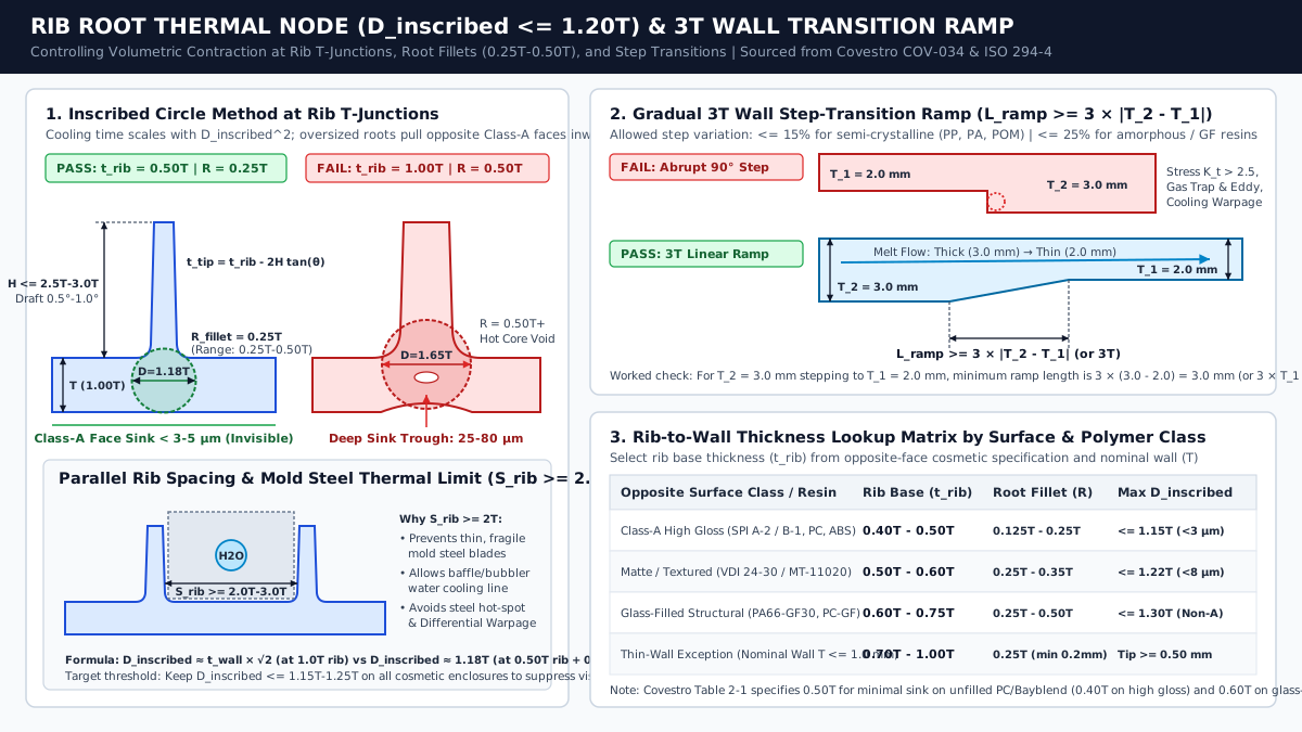
Physics of the Inscribed Circle Criterion (D_inscribed <= 1.20T)
Whenever a rib of base thickness t_rib joins a primary wall of thickness T with root fillet radius R_fillet, the T-junction creates a localized thermal mass node. Toolmakers evaluate the effective cooling thickness of that intersection by fitting the largest possible circle inside the T-junction cross-section (D_inscribed):
- Compliant rib root (
t_rib = 0.50T,R_fillet = 0.25T): The inscribed circle diameter evaluates toD_inscribed ≈ 1.18T(1.15T to 1.22T). Because local thermal mass exceeds the nominal wall by less than20%, the frozen exterior skin resists inward pull and restricts opposite-face sink depression below3 to 8 µm, which is invisible on matte textures. On high-gloss dark amorphous surfaces (SPI A-2orB-1), human specular vision detects depressions down to3 µm, so Covestro reduces the rib root ratio to0.40T(D_inscribed ≈ 1.10T). - Oversized rib root (
t_rib = 1.00T,R_fillet = 0.50T): Matching rib thickness to wall thickness inflates the inscribed circle toD_inscribed ≈ 1.65T. Because cooling time scales withD_inscribed^2, the junction takes2.72 times(1.65^2) longer to freeze than the wall, pulling a25 to 80 µmwitness trough across the Class-A surface.
Complete Rib Geometry Proportions Table
| Rib geometric feature | Symbol | Recommended ratio to wall T |
Engineering rationale & tooling constraint |
|---|---|---|---|
| Rib base (High-gloss Class-A face) | t_rib |
0.40T to 0.50T |
Keeps D_inscribed <= 1.15T so sink stays under 3 µm on glossy dark PC, ABS, or PMMA |
| Rib base (Matte / textured face) | t_rib |
0.50T to 0.60T |
Standard DFM rule where VDI >= 24 or MT-11020 scatter masks micro-depressions up to 5-8 µm |
| Rib base (Glass-filled grades) | t_rib |
0.60T to 0.75T |
Low parallel shrinkage (0.2%-0.5%) and stiff GF30 skins resist sink; wider base aids fiber fill |
Rib base (Thin wall T <= 1.0 mm) |
t_rib |
0.70T to 1.00T |
Prevents the drafted rib tip from dropping below the 0.45-0.50 mm minimum flow width |
| Maximum rib height | H_rib |
<= 2.5T to 3.0T (3x-5x t_rib) |
Draft tapers the tip by t_tip = t_rib - 2 * H_rib * tan(theta_draft). Use multiple short ribs instead of one tall rib |
| Minimum parallel rib spacing | S_rib |
>= 2.0T to 3.0T (clear gap) |
Narrower spacing leaves thin mold steel blades that cannot fit cooling lines, creating steel hot spots |
| Rib root fillet radius | R_fillet |
0.25T to 0.50T (0.125T min) |
Eliminates root notch stress (K_t > 2.5 when R < 0.1 mm) without enlarging D_inscribed |
| Rib draft angle | theta_rib |
0.5° to 1.0° per side |
Shrinkage clamps ribs onto core steel; draw-polishing steel in the pull direction prevents rib tearing |
Worked Example (Internal Stiffening Rib Array on T = 2.50 mm PC/ABS Wall with VDI 24 Texture):
  1. Rib root thickness: t_rib = 0.50 x 2.50 mm = 1.25 mm.
  2. Root fillet radius: R_fillet = 0.25 x 2.50 mm = 0.625 mm (specify 0.60 ± 0.10 mm on drawing).
  3. Rib height & tip check at H_rib = 5.00 mm (2.0T) with theta_rib = 0.75° per side:
     t_tip = 1.25 - 2 x 5.00 x tan(0.75°) = 1.25 - 0.131 = 1.12 mm (> 0.50 mm flow limit).
  4. Minimum clear spacing: S_rib = 2.5 x 2.50 mm = 6.25 mm between adjacent rib walls.
Takeaway: Size rib roots at 0.40T-0.50T under glossy surfaces and 0.50T-0.60T under textured surfaces, cap rib height at 2.5T-3.0T, and leave >= 2.0T-3.0T between parallel ribs so mold steel cools evenly.
3. Plastic Boss and Rib Design: Wall Isolation, Volcano Relief, and Fastener Sizing
Because mechanical hoop stress from fastener installation often demands a boss wall thickness (t_boss) thicker than 0.50T, plastic boss and rib design requires isolating the boss thermal mass from both the vertical side walls and the horizontal floor wall.
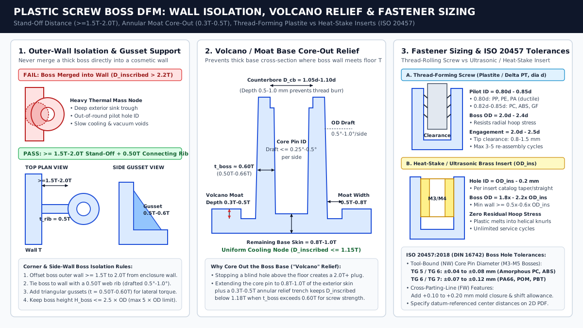
Outer-Wall Stand-Off Isolation and Volcano Base Core-Out
Merging a screw boss (OD = 6.0 to 7.5 mm) directly into a 2.5 mm side wall creates a thermal node with D_inscribed > 2.2T, producing a deep vertical sink groove along the exterior wall and distorting the pilot bore into an oval. Apply four geometric rules to isolate the boss:
- Outer-wall stand-off (
>= 1.5T to 2.0T): Offset the boss outer perimeter at least1.5T to 2.0Tinward from the exterior wall and tie it back with a0.50Tradial web rib and0.50T to 0.60Ttriangular floor gussets. - Full-depth core pin penetration (
0.80T to 1.00Tfloor skin): Extend the central bore core pin down to within0.80T to 1.00Tof the exterior floor surface so no thick solid pedestal remains under the hole. - Annular volcano / moat relief (
0.30T to 0.50Tdepth): Where fastener hoop stress forcest_boss > 0.60Ton a cosmetic floor, cut an annular cored-out relief trench (volcano boss) of depth0.30T to 0.50Tand width0.50T to 0.80Taround the outer base perimeter of the boss to neck down heat conduction and keepD_inscribed <= 1.15T. - Top lead-in counterbore (
D_cb = 1.05d to 1.10d): Add a0.5 to 1.0 mmdeep flat counterbore at the top of the bore to center the fastener, relieve top-edge hoop stress, and prevent the first thread crest from raising a plastic burr.
Thread-Forming Plastite Screws vs Heat-Stake Brass Inserts (ISO 20457)
- Trilobular thread-forming screws (
Plastite 45 / 48-2,EJOT Delta PT): Cold-flow thermoplastic into the thread root rather than cutting polymer chains. To resist radial hoop expansion without splitting the boss, size the pilot hole atID = 0.80d to 0.85d(0.80dfor ductile PP/PA;0.82d-0.85dfor stiff PC, ABS, or GF grades) and the boss ring atOD = 2.0d to 2.4dwith2.0d to 2.5dthread engagement. - Ultrasonic and heat-stake knurled brass inserts (
SPIROL,PEM SI,Bossard,Dodge): Pressed into a molded receiving hole using thermal or ultrasonic energy so plastic melts into opposed helical knurls and solidifies with zero residual radial hoop stress. Size the boss atOD = 1.8x to 2.2x OD_insert(0.50x to 0.60x OD_insertwall thickness) for unlimited service disassembly cycles.
When releasing 2D drawings (see our manufacturing specification handoff checklist and mechanical design engineer DFM handover guide), specify boss hole tolerances per ISO 20457:2018 (which superseded DIN 16742). Tool-bound (NW) core-pin diameters hold Tolerance Grade TG 5 or TG 6 (±0.04 to ±0.08 mm in amorphous PC/ABS; TG 6/7 ±0.07 to ±0.12 mm in semi-crystalline PA66/POM), whereas cross-parting-line (FW) dimensions require an extra +0.10 to +0.20 mm mold closure allowance:
| Fastener system & nominal size | Screw / insert OD (d or OD_ins) |
Molded pilot / receiving bore (ID) |
Recommended boss OD | Engagement & hole depth | Core-pin draft & ISO 20457 (NW) tolerance |
|---|---|---|---|---|---|
Plastite / Delta PT M2.5 (PC/ABS, ABS) |
2.5 mm |
2.05-2.12 mm (0.82d-0.85d) |
5.5-6.0 mm (2.2d-2.4d) |
L_eng = 5-6 mm; H >= 6.8 mm |
Draft <= 0.25°; TG 5 (±0.04 mm) |
Plastite / Delta PT M3.0 (PC/ABS, ABS) |
3.0 mm |
2.46-2.55 mm (0.82d-0.85d) |
6.6-7.2 mm (2.2d-2.4d) |
L_eng = 6-7.5 mm; H >= 8.5 mm |
Draft <= 0.25°-0.5°; TG 5 (±0.05 mm) |
Plastite / Delta PT M3.0 (PP, PE, PA66) |
3.0 mm |
2.40-2.46 mm (0.80d-0.82d) |
6.0-6.6 mm (2.0d-2.2d) |
L_eng = 6.5-7.5 mm; H >= 8.5 mm |
Draft <= 0.25°-0.5°; TG 6 (±0.07 mm) |
Plastite / Delta PT M4.0 (PC/ABS, GF30) |
4.0 mm |
3.28-3.40 mm (0.82d-0.85d) |
8.0-9.6 mm (2.0d-2.4d) |
L_eng = 8-10 mm; H >= 11.2 mm |
Draft <= 0.25°-0.5°; TG 5/6 (±0.06 mm) |
Heat-Stake Brass Insert M3 (OD_ins = 4.6 mm) |
4.6 mm |
4.35-4.45 mm (1° taper) |
8.3-9.2 mm (1.8x-2.0x) |
Insert 5.0 mm; H >= 6.0 mm |
Taper 0.5°-1.0°; TG 5 (±0.05 mm) |
Heat-Stake Brass Insert M4 (OD_ins = 5.6 mm) |
5.6 mm |
5.35-5.45 mm (1° taper) |
10.1-11.2 mm (1.8x-2.0x) |
Insert 6.4 mm; H >= 7.5 mm |
Taper 0.5°-1.0°; TG 5/6 (±0.06 mm) |
Takeaway: Stand every screw boss >= 1.5T-2.0T off exterior walls with 0.50T connecting ribs, relieve thick floor intersections with a 0.30T-0.50T volcano moat, and size pilot holes separately for thread-forming screws (0.80d-0.85d) versus heat-stake inserts (ISO 20457 TG 5/6).
4. Draft Angles and the SPI / VDI 3400 / Mold-Tech Texture Adder Lookup Matrix
As a molded part cools, volumetric shrinkage pulls outer walls slightly away from the female cavity while clamping internal walls, ribs, and bosses onto the male core. When a cavity face carries an EDM spark finish (VDI 3400) or a chemical photo-etch texture (Mold-Tech), thousands of microscopic undercut pockets of depth d_tex lock onto the plastic skin.
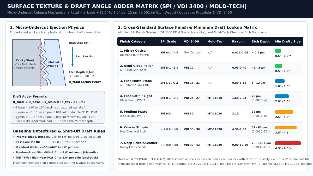
Micro-Undercut Physics and the Texture Draft Adder Equation
To let the solidified plastic wall clear the texture peaks upon initial mold opening without drag scuffing, calculate the total required draft angle (theta_total) by adding a texture increment (Delta_theta_texture) to the baseline untextured draft (theta_base):
theta_total = theta_base + k_resin x (d_tex / 0.025 mm)
  - theta_base >= 1.0° to 1.5° (baseline untextured vertical wall draft; +1.0° per 25 mm depth beyond 50 mm)
  - k_resin    =  +1.0° per 0.025 mm (25 µm / 0.001 in) for ductile resins (PP, PE, POM, PA)
  - k_resin    =  +1.5° per 0.025 mm (25 µm / 0.001 in) for stiff amorphous or GF resins (PC, ABS, PMMA, PA66-GF30)
  - Shutoffs   >= 3.0° to 5.0° minimum on steel-on-steel sliding kiss-off faces
Cross-Standard Surface Finish and Draft Angle Lookup Matrix
| Finish category | SPI grade | VDI 3400 grade | Mold-Tech / rapid equivalent | Roughness Ra (µm) |
Texture depth (d_tex) |
Recommended draft per side (Ductile / Stiff) |
Rapid tooling limit (Protolabs) |
|---|---|---|---|---|---|---|---|
| 1. Mirror Optical Polish | SPI A-1 / A-2 | N/A (Diamond Buff) | N/A | 0.012-0.05 µm |
< 0.1 µm (0.0000 in) |
0.5°-1.0° (1.0°-2.0° on PC/TPE anti-vacuum) |
0.5°-1.0° |
| 2. Semi-Gloss Grit Polish | SPI B-1 / B-2 | VDI 12 | N/A (600 Grit) |
0.05-0.40 µm |
1-3 µm (0.0001 in) |
0.5°-1.0° per side |
1.0°-2.0° |
| 3. Fine Matte Stone / EDM | SPI C-1 / C-2 | VDI 18 - VDI 21 | N/A (400 Stone) |
0.80-1.12 µm |
5-12 µm (0.0002-0.0005 in) |
1.0°-1.5° per side |
1.0°-2.0° |
| 4. Fine Satin / Light Etch | SPI D-1 / D-2 | VDI 24 - VDI 27 | MT-11010 (PM-T1) |
1.60-2.24 µm |
25 µm (0.025 mm / 0.0010 in) |
2.0°-2.5° (PP) / 2.5°-3.0° (PC/ABS) |
3.0° min (PM-T1) |
| 5. Medium Commercial Matte | SPI D-3 | VDI 30 | MT-11020 (PM-T2) |
3.15 µm |
38 µm (0.038 mm / 0.0015 in) |
2.5°-3.0° (PP) / 3.25°-3.75° (PC/ABS) |
5.0° min (PM-T2) |
| 6. Medium-Coarse Stipple | N/A (Etched) | VDI 33 - VDI 36 | MT-11030 | 4.50-6.30 µm |
51-65 µm (0.0020-0.0025 in) |
3.0°-4.0° (PP) / 4.0°-5.0° (PC/ABS/GF) |
4.0°-5.0° min |
| 7. Coarse Pebble / Leather | N/A (Etched) | VDI 39 - VDI 42 | MT-11040 / 11050 | 9.00-12.50 µm |
76-100+ µm (0.0030-0.0040 in) |
4.5°-5.5° (PP) / 5.5°-7.5°+ (PC/ABS/GF) |
5.5°-7.5°+ min |
Worked Example (Draft Angle Selection for MT-11020 / VDI 30 on a 35 mm Deep PC/ABS Wall):
  1. Baseline draft: theta_base = 1.50° per side.
  2. Texture adder (d_tex = 0.038 mm, k_resin = +1.5° / 0.025 mm):
     Delta_theta_texture = 1.5° x (0.038 / 0.025) = +2.28° -> theta_total = 1.50° + 2.28° = 3.78° (specify 3.8°-4.0°).
  3. Horizontal wall offset over H_wall = 35.0 mm: Delta_x = 35.0 x tan(3.8°) = 2.32 mm.
     Match internal core draft (theta_core = 3.8°) to exterior cavity draft so nominal wall T stays constant!
Takeaway: Calculate total exterior wall draft from the exact VDI 3400 or Mold-Tech etch depth (+1.0° to +1.5° per 25 µm), and apply the identical draft angle to the matching internal core wall so nominal wall thickness T stays constant from parting line to base.
5. Pre-Tooling CAD Section Verification Protocol
Before exporting a STEP AP214/AP242 assembly and 2D inspection drawings for a molder DFM quote, run this five-step quantitative section audit across your CAD model:
- Inscribed Sphere Wall Audit (
D_inscribed <= 1.20T): Run a 3D rolling-ball thickness analysis. Verify that the shell stays at nominalT, step transitions followL_ramp >= 3 x |T_2 - T_1|, and no rib or boss intersection exceeds1.15Tbehind a gloss surface or1.22Tbehind a textured surface. - Pull-Direction Draft Color Map: Set the pull vector normal to the parting plane and verify
>= 0.5°-1.0°on internal ribs and boss ODs,<= 0.25°-0.5°on boss pilot IDs,>= 3.0°-5.0°on steel-on-steel shutoffs, and matched core/cavity texture draft (2.5°-6.0°) on perimeter walls. - Screw Boss Isolation & Volcano Relief Check: Confirm that every boss is offset
>= 1.5T-2.0Tfrom exterior side walls, connected via0.50Tribs, cored down to within0.80T-1.00Tof the bottom skin, and surrounded by a0.30T-0.50Tvolcano moat wherevert_bossexceeds0.60T. - Fastener Bore & ISO 20457 Tolerance Callout: Check that pilot hole diameters match
0.80d-0.85dfor thread-forming screws or the exact brass insert catalog bore, with a1.05d-1.10dtop counterbore and ISO 20457 TG 5 or TG 6 tool-bound (NW) bilateral limits on the 2D drawing. - Shrinkage Anisotropy & Parting-Line Stack-Up: Cross-check critical assembly fits in our mechanical design engineer DFM handover guide to verify that cross-parting-line (
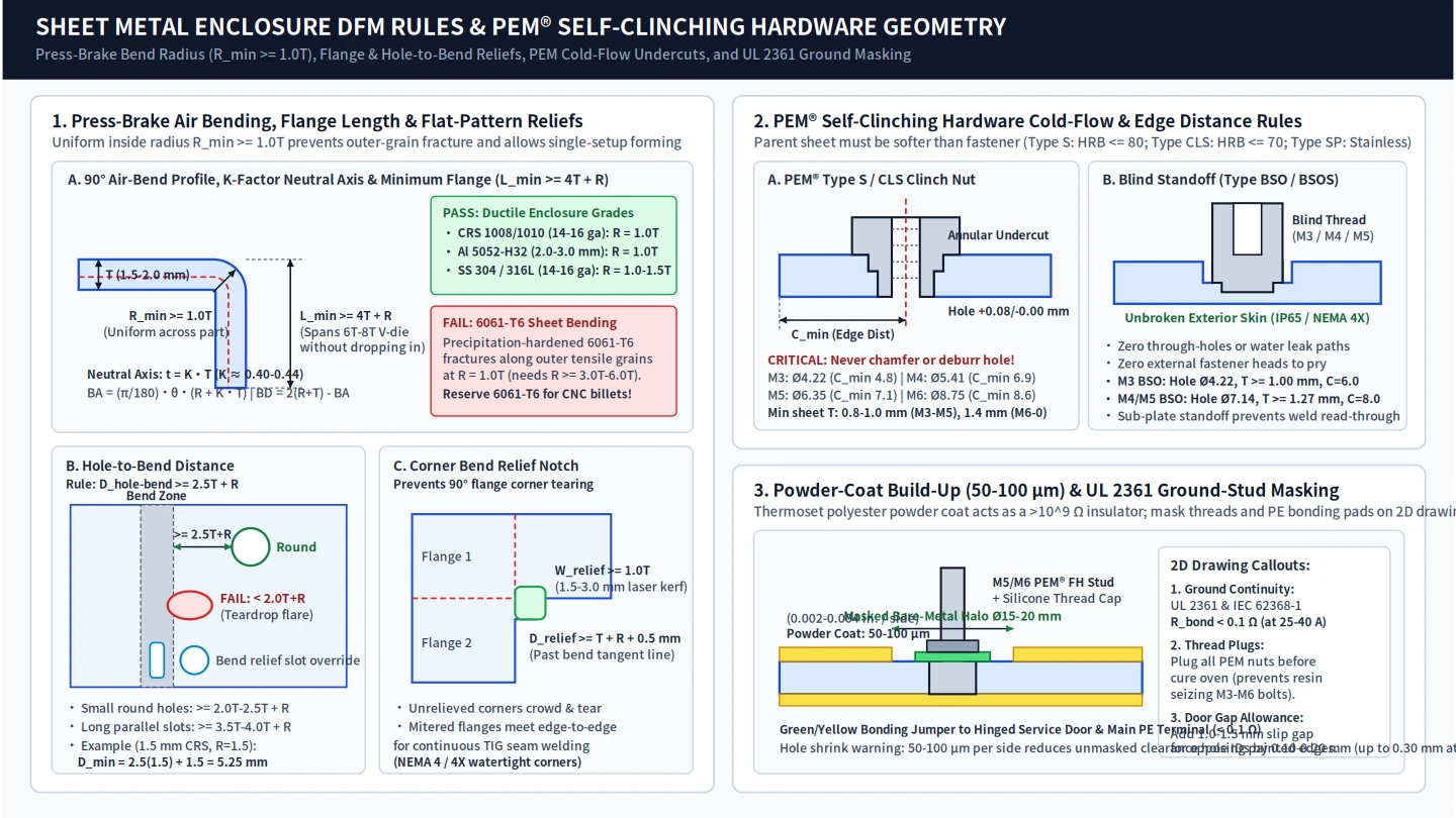
FW) dimensions include+0.10 to +0.20 mmmold closure allowance. For low-to-medium volume floor-standing cabinets that pair brake-formed sheet metal and PEM hardware with machined or printed bezels, see our kiosk enclosures guide to sheet metal DFM, thermal airflow, and service access, or explore more hardware manufacturing guides in the DFM and Hardware category.
Takeaway: Complete both the 3D inscribed-sphere thickness audit and the pull-direction draft check before freezing your STEP and 2D drawing release package.