A boss that is too thick or a face with no draft shows up later as sink marks, warped parts or parts damaged on ejection, and the fix can mean recutting the mold. Design the part around one even wall within the recommended range for your plastic, make ribs and boss walls thinner than that wall, give every face that slides out of the mold at least half a degree of draft and round the inside corners.
Injection molding design guidelines keep a part moldable by controlling how the plastic flows, cools and leaves the mold. For polycarbonate, Covestro’s design guide (October 2015) sets rib thickness at 50% of the wall for minimal sink, 40% under a high-gloss surface, and asks for at least 0.5° of draft per side on ribs; Protolabs recommends 2° of draft in most situations and lists wall ranges such as 0.889–3.81 mm for polypropylene (accessed October 7, 2026). Exact values depend on the resin grade, surface finish and molder.
This page compiles the rules from a resin maker’s design guide and a molder’s published guidelines, both read on October 7, 2026, and explains why each rule exists so you can judge exceptions. It covers conventional thermoplastic injection molding of parts such as enclosures and housings, and ends with a checklist to run before you release a drawing.
Quick specs
| Rule | Typical value or source | Why it matters |
|---|---|---|
| Nominal wall (the part’s main, typical wall thickness) | Within your resin’s range, for example ABS 1.143–3.556 mm, PC 1.016–3.81 mm, PP 0.889–3.81 mm (Protolabs) | Too thin fails to fill; too thick sinks, voids and lengthens the cycle |
| Wall variation | Up to about 25% for most amorphous or filled resins (Covestro) | Larger jumps cause warping and filling problems |
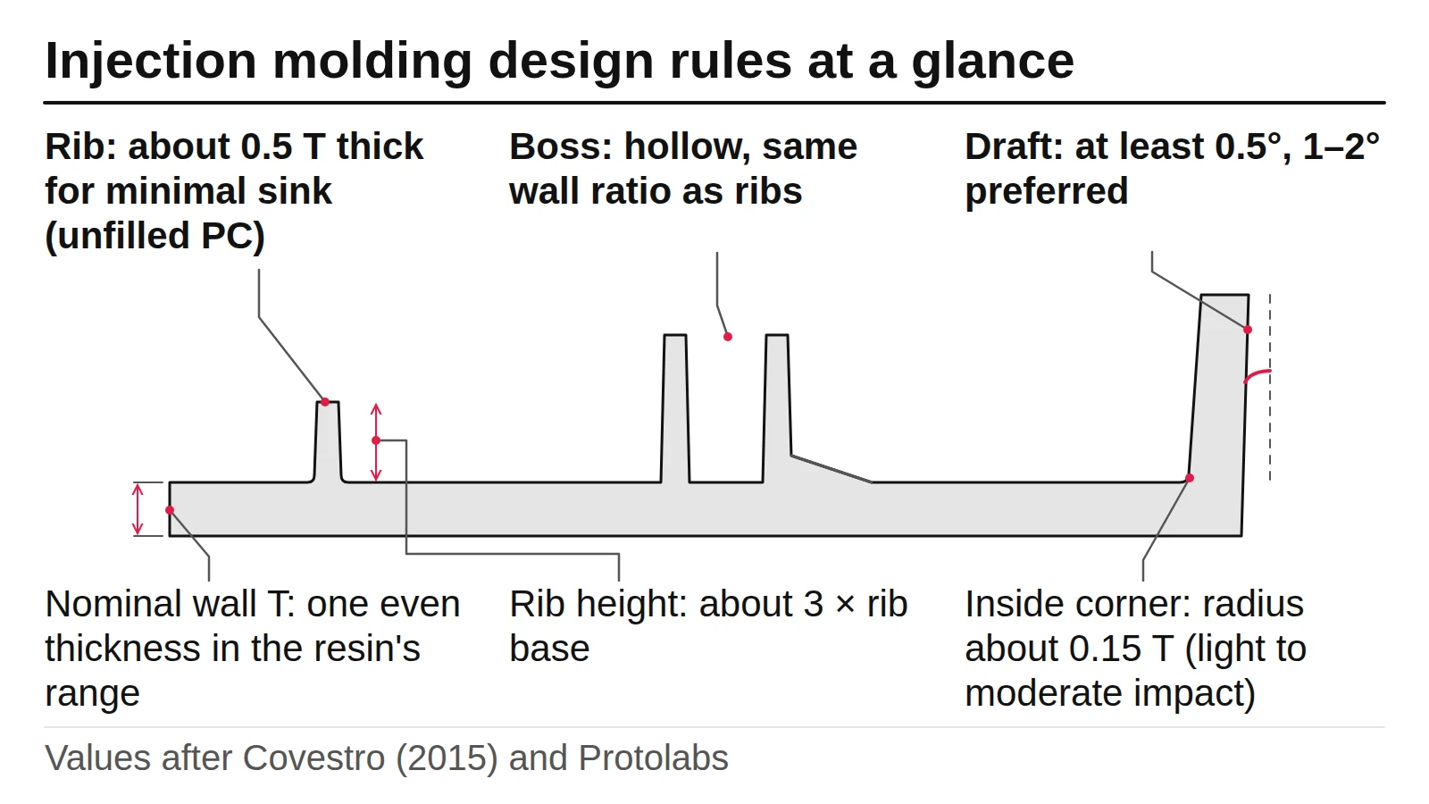
| Rib thickness at the base | 50% of the wall for minimal sink, 66% for slight sink, on unfilled PC (Covestro) | Thick ribs leave sink marks on the opposite face |
| Rib height and spacing | About 3 × rib base thickness; at least 2 × wall between short ribs (Covestro) | Tall ribs get too thin to fill after draft; close ribs cool poorly |
| Boss wall (bosses are posts that take screws or inserts) | Same ratio as ribs; base fillet about 0.015 in (Covestro) | A solid, thick boss sinks and voids |
| Draft | At least 0.5° per side on ribs and most PC parts, 1° preferred, 3–5° for high-heat PC and TPU (Covestro); 2° in most situations, 3° or more for textures and shut-offs (Protolabs) | Without draft the part drags or sticks in the mold |
| Inside corner radius | Around 0.15 × thickness as a compromise for light to moderate impact loads; stress rises sharply below about 0.2 (Covestro) | Sharp corners crack under impact and fatigue |
Why do molded parts need these rules?
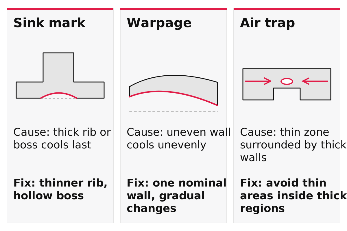
Molten plastic has to fill the cavity, cool evenly and slide out of the mold, and part geometry affects all three steps. Thick sections cool last and shrink more, so they pull the surface in (sink marks) or leave voids inside. Uneven walls cool at different rates and bend the part (warpage). Thin areas surrounded by thick ones trap air, and faces with no taper drag on the steel during ejection.
Covestro’s guide makes the point about stiffness that changes how designers think about walls: in a simple flat section, each 10% increase in wall thickness adds roughly 33% stiffness, but also adds weight, cycle time and material. It recommends ribs, curves and corrugations to stiffen a part instead. Most of the rules below follow from that: keep one wall, and add stiffness with features that are thinner than the wall.
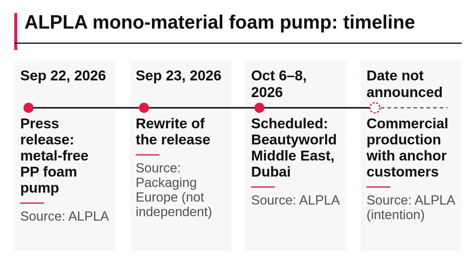
These rules matter even for small parts such as pump heads. ALPLA says its new foam pump is made entirely of polypropylene with no metal parts; our ALPLA foam pump reading asks what such a design has to achieve with molded plastic alone, since the mechanism itself has not been published.
Takeaway: Read every rule below as a way to make the part fill, cool and eject evenly.
How thick should the walls be?
Choose one nominal wall inside the range recommended for your plastic and keep it as even as the design allows. Protolabs publishes recommended ranges per material, adapted from manufacturingcenter.com; the table lists the plastics most common in student enclosure projects.
| Plastic | Recommended wall thickness (Protolabs) |
|---|---|
| ABS | 1.143–3.556 mm (0.045–0.140 in) |
| Polycarbonate | 1.016–3.81 mm (0.040–0.150 in) |
| Polypropylene | 0.889–3.81 mm (0.035–0.150 in) |
| Polyethylene | 0.762–5.08 mm (0.030–0.200 in) |
| Polystyrene | 0.889–3.81 mm (0.035–0.150 in) |
| Nylon | 0.762–2.921 mm (0.030–0.115 in) |
| Acetal | 0.762–3.048 mm (0.030–0.120 in) |
| Acrylic | 0.635–12.7 mm (0.025–0.500 in) |
Covestro adds the rules for how even the wall must be. Avoid thin areas surrounded by thicker regions, because they trap gas, and avoid designs that make the plastic flow from thin into thick sections. Most amorphous or filled resins tolerate wall variation of about 25% without significant filling, warpage or appearance problems; the guide treats unfilled crystalline resins separately because of their high molding shrinkage. Very thin walls are not automatically cheaper: Covestro notes that parts with main walls under 1.5 mm may need special high-performance molding equipment, which can cancel out the material saved.
If a printed prototype already exists, measure its walls before you redesign. A shape that printed well can have thick corners and solid bosses that a mold will not tolerate; the CNC and printing comparison explains at what quantity the move to molding usually happens.
Common mistake: Thickening the whole wall to make a part stiffer. Covestro recommends ribs, curves and corrugations instead, because they add stiffness with very little increase in weight, cycle time or cost.
Takeaway: Pick one wall from your material’s range, keep variations gradual and stiffen with ribs rather than thickness.
How should you design ribs and bosses?
Make ribs and boss walls thinner than the wall they stand on, about half of it for parts where sink would show, and give them draft and a small fillet at the base. A boss is a post that takes a screw or insert; a rib is a thin wall that stiffens the part. Covestro’s Table 2-1 gives rib thickness at the base as a percentage of the wall for its resins:
| Resin (Covestro) | Rib thickness for minimal sink | Rib thickness for slight sink |
|---|---|---|
| Polycarbonate (Makrolon) | 50% (40% if high gloss) | 66% |
| Polycarbonate, glass-filled | 60% | 75% |
| PC/ABS (Bayblend) | 50% | 66% |
| PC/ABS, filled | 60% | 75% |
| PC/PET (Makroblend) | 50% | 66% |
| PC/PET, filled | 55% | 70% |
| TPU (Texin, Desmopan) | 50% | 66% |
The rest of the rib rules, all from Covestro’s guide:
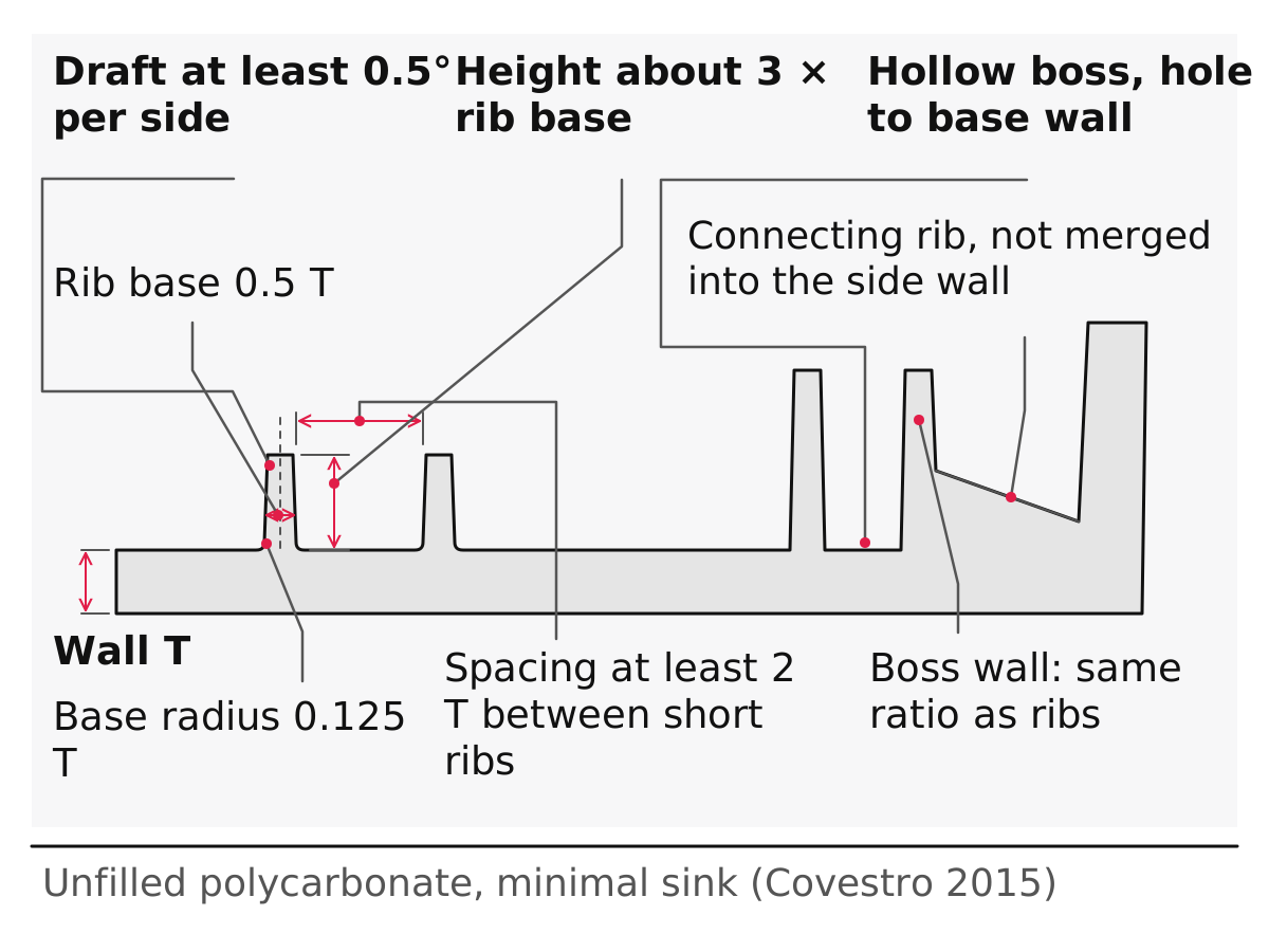
- Height. Limit rib height to about three times the rib base thickness. Draft makes tall ribs thin at the top and hard to fill, and very tall ribs can buckle; two shorter ribs are often better than one tall one.
- Spacing. Leave at least two times the wall thickness between short ribs so the mold can cool between them.
- Draft and fillet. Give ribs at least 0.5° of draft per side. The guide’s rib diagram labels a base radius of 0.125 T for a rib 0.5 T thick on a wall of thickness T.
- Very thin walls. On walls under 1.5 mm, ribs can often be thicker than the table; on walls of 1.0 mm or less, make the rib equal to the wall.
- Gussets. Keep these rib-like supports at one-half to two-thirds of the wall they attach to.
Bosses follow the same logic. Keep the ratio of boss wall to nominal wall the same as for ribs, blend the base with a fillet (Covestro suggests about 0.015 in for most applications), and run the hole down to the base wall so no thick plug is left. Do not merge a boss into a side wall; place it away from the wall and connect it with ribs. Covestro warns that bosses taller than five times their outside diameter can cause filling problems at the top or a thick section at the base. Machined prototypes handle these details differently, as the enclosure feature table shows.
Common mistake: Modelling a screw boss as a solid cylinder joined to the corner of two walls. It creates a thick section, which Covestro links to sink and voids.
Takeaway: Size ribs and bosses as a fraction of the wall, not as a fixed dimension, and check the fraction for your resin.
How much draft does a molded part need?
Give every face that slides out of the mold a taper: at least 0.5°, about 1–2° where the design allows, and more on textured surfaces. Draft lets the part release without scuffing or sticking. The two sources agree on the principle and differ slightly on the numbers, so the table shows both with their conditions.
| Situation | Covestro guide | Protolabs guidelines |
|---|---|---|
| Minimum on plain faces | 0.5° for most PC-based materials; 0.5° per side on ribs | 0.5° on vertical faces |
| Preferred | 1° for easy ejection | 2° in most situations |
| Textured faces | 1° plus 1° for every 0.001 in of texture depth | 3° minimum for light texture PM-T1; 5° or more for PM-T2 |
| Shut-offs (faces where mold halves slide past each other and seal to form a hole) | Not given | 3° minimum |
| Special resins | 3–5° for high-heat PC (Apec) and TPU (Texin, Desmopan) | Not given |
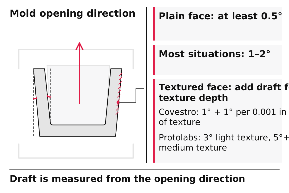
Covestro adds that features formed in blind holes or pockets, such as most bosses, ribs and posts, should taper thinner as they go deeper into the mold, and that polished mold surfaces generally need less draft than machined ones. Too little draft can force molders to use release agents or special coatings, which lengthens cycles and raises part cost.
Takeaway: Decide the surface texture first, then set draft from it; a textured face needs several degrees more than a polished one.
How should corners be rounded?
For parts under light to moderate impact loads, round inside corners to about 0.15 times the wall thickness, and avoid sharp inside corners entirely; leave outside corners square unless the design calls for a radius. Covestro’s guide shows the stress concentration factor climbing sharply once the radius-to-thickness ratio drops below about 0.2, and recommends a ratio of about 0.15 as a compromise between performance and appearance for parts with light to moderate impact loads. Very large radii create thick sections, which bring sink and voids back.
Two practical points from the same guide: write critical inside radii on the drawing as a range, because a maximum value alone lets the mold maker leave a corner sharp, and avoid a blanket “all edges radius” note that rounds outside corners needlessly and adds mold cost. Protolabs notes that some corners on its parts come out with a radius anyway, because its molds are cut by CNC milling, and it identifies those radii before the mold is made.
Takeaway: Specify inside radii as a range on the drawing and keep outside edges sharp unless the design needs them rounded.
What tolerance can a molded part hold?
A molded part’s tolerance combines how accurately the mold is cut and how much the plastic shrinks, so it depends on both the molder and the resin. Protolabs states that it can typically maintain a machining tolerance of ±0.003 in (0.08 mm) on its molds, with an included resin tolerance that can be greater than, but no less than, ±0.002 in per inch (0.002 mm per mm).
As a worked example with assumed inputs: on a 100 mm feature, a resin tolerance of ±0.002 mm per mm alone allows ±0.2 mm, before the ±0.08 mm machining tolerance is considered. Ask your molder how they combine the two for your material. Shrinkage also interacts with the rib rules: Covestro notes that thin ribs in unfilled resins solidify earlier and can make part ends warp away from the ribbed side, while glass-filled resins can warp the other way.
Takeaway: Ask the molder for a tolerance on your resin and part size; do not assume a printed or machined prototype’s accuracy carries over.
Pre-drawing checklist
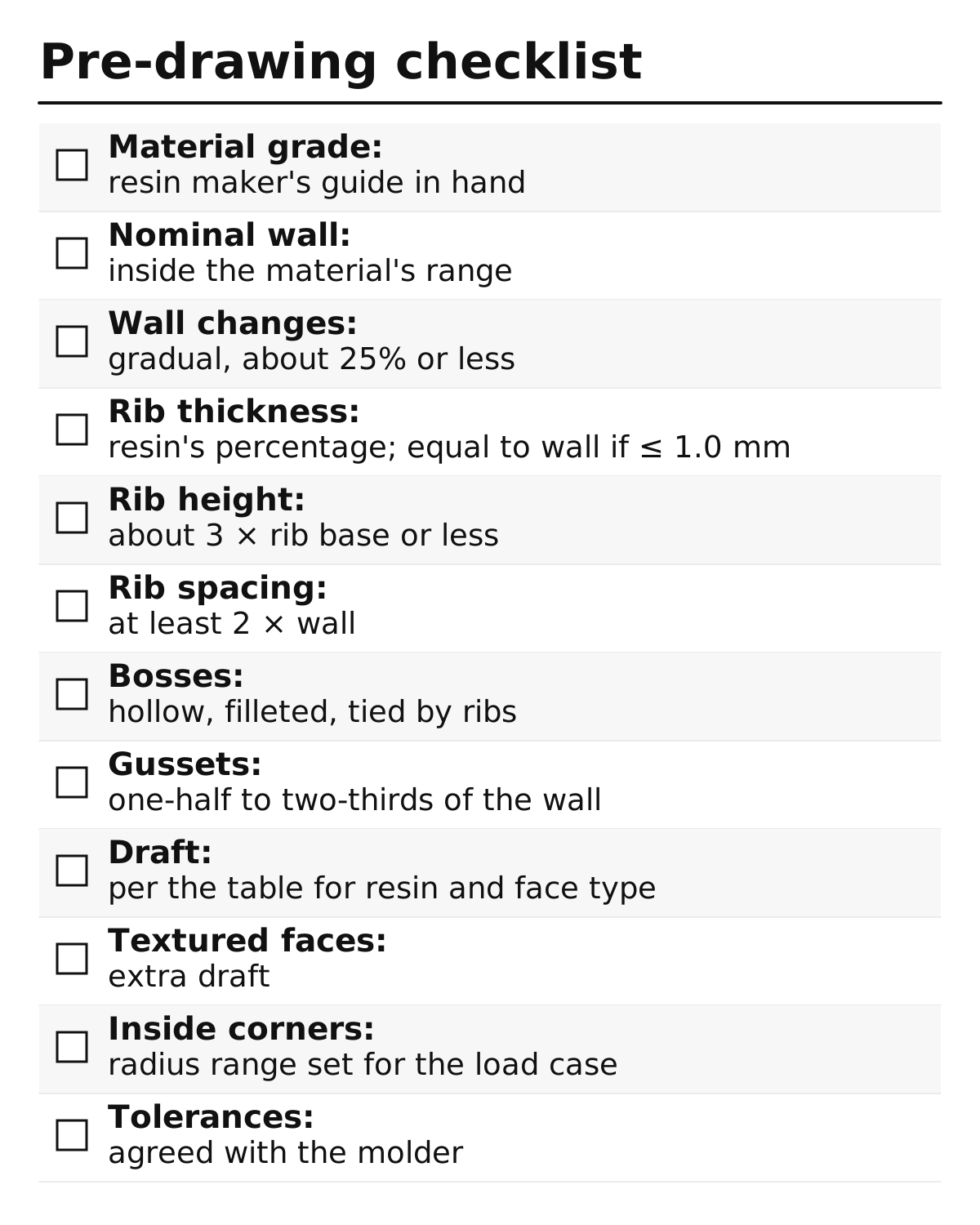
Run this list before you release a drawing or send a model for a molding quote. It is our summary of the rules above; the section column links back to the conditions behind each check.
| # | Check | Pass when | Section |
|---|---|---|---|
| 1 | Material grade chosen | You have the resin maker’s guide for that grade | Walls |
| 2 | Nominal wall | Inside the recommended range for the material | Walls |
| 3 | Wall changes | Gradual, within about 25% for amorphous or filled resins | Walls |
| 4 | Rib thickness | Matches the resin’s percentage for your surface finish; on walls of 1.0 mm or less, equal to the wall; ribs still fill | Ribs and bosses |
| 5 | Rib height | About 3 × rib base thickness or less | Ribs and bosses |
| 6 | Rib spacing | At least 2 × wall between short ribs | Ribs and bosses |
| 7 | Bosses | Hollow, same wall ratio as ribs, filleted, tied to walls by ribs, not merged into them | Ribs and bosses |
| 8 | Gussets | One-half to two-thirds of the wall | Ribs and bosses |
| 9 | Draft | Meets the draft table for your resin and face type: 0.5° minimum only where the sources allow it, 3–5° for high-heat PC and TPU, 3° on shut-offs | Draft |
| 10 | Textured faces | Extra draft added for the chosen texture grade | Draft |
| 11 | Inside corners | Radius range set for the load case, written on the drawing; about 0.15 × thickness for light to moderate impact | Corners |
| 12 | Tolerances | Agreed with the molder for your resin and part size | Tolerance |
If you are still prototyping, the rapid prototyping guide places this check at the pre-production stage. A finished checklist with before-and-after sections also makes strong evidence in a design portfolio. More articles on design for manufacturing are collected under DFM and the injection molding tag.
Takeaway: Release a drawing only when all twelve checks pass or each exception has a reason agreed with the molder.
When this does not apply
These rules describe conventional thermoplastic injection molding as covered by the two sources. They do not hold, or need adjusting, in these cases:
- Other resins. Covestro’s percentages are for its polycarbonate-based resins and TPU. Semi-crystalline plastics such as PP and nylon shrink more; ask the resin maker for their values.
- Other processes. Gas-assist molding, liquid silicone rubber, overmolding, structural foam and thin-wall molding follow their own guides.
- Cosmetic surfaces. High-gloss and dark surfaces show sink more readily; Covestro drops the minimal-sink rib to 40% of the wall for high gloss.
- Mold details. Gates, cooling, ejectors and slides are mold design questions this page does not cover.
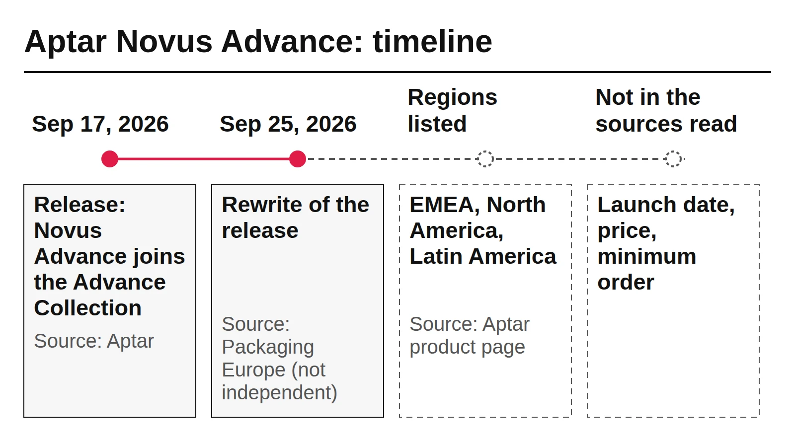
- Pump and dispenser parts. Products such as the pumps in our news readings, the Aptar Novus Advance pump and the Aptar L’Occitane pump, involve moving parts and precision fits that go beyond general part rules.
- Older figures. The Covestro guide dates from October 2015; we found no newer edition. Confirm values with current supplier data.
Takeaway: Use these rules as a starting point and confirm every number with your resin supplier and molder.
How this page was put together
We compiled this page on October 7, 2026 from public sources: Covestro LLC’s Engineering Polymers Part and Mold Design guide (COV-034, October 2015), written for its polycarbonate, PC blend and TPU resins, and Protolabs’ current plastic injection molding design guidelines, whose wall thickness table is itself adapted from manufacturingcenter.com, plus a Protolabs design tip for the definition of shut-offs. Covestro sells resins and Protolabs sells molding, so each value is attributed to its source and kept with its conditions. The worked tolerance example uses assumed inputs. The checklist and the order of the rules are our editorial summary. Nothing here comes from our own molding trials.
Takeaway: Before using a value, open the source and confirm it applies to your resin grade, surface and molder.
Related reading:
- 3D printing vs CNC machining for prototypes — Choose how to make the prototypes before the mold.
- Rapid prototyping with 3D printing — Plan the print-test rounds that lead up to molding.
- ALPLA mono-material foam pump — Read what ALPLA says about an all-polypropylene dispenser and what it leaves open.