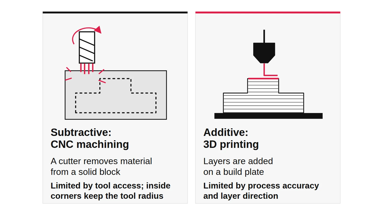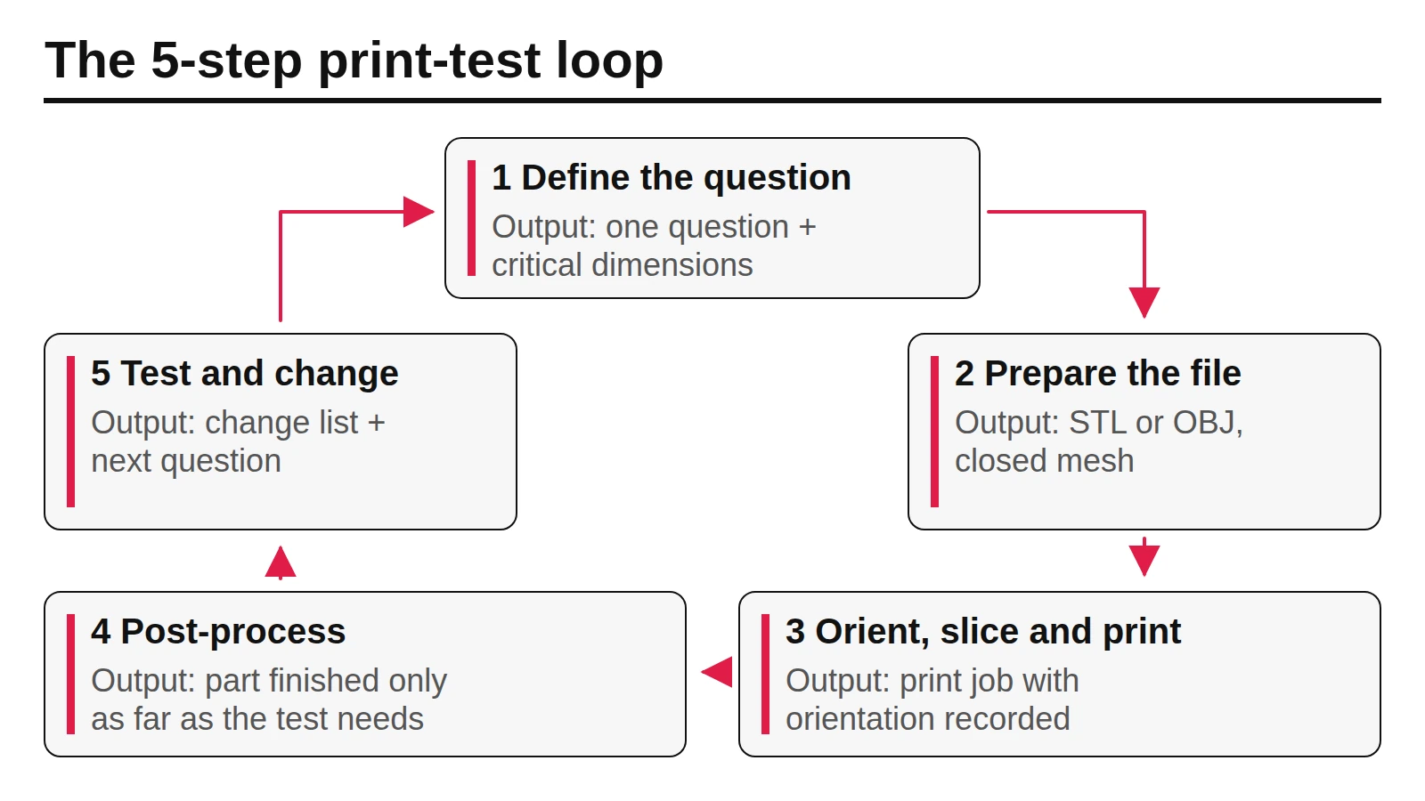
Choosing a print process before deciding what the prototype has to prove wastes print hours and teaches the wrong lesson. Rapid prototyping with 3D printing works as a loop: name the question the model must answer, prepare the file, print it in the process that suits that question, finish it, test it and change the design.
Rapid prototyping with 3D printing means using additive processes to turn CAD into physical test models fast enough to change the design between rounds. For most student and early hardware projects, FDM suits cheap shape and size checks, SLA suits fine detail and smooth surfaces, and SLS suits tougher functional parts that need no support structures. Accuracy differs widely: Protolabs Network lists about ±0.5 mm for desktop FDM, ±0.2 mm for industrial FDM and ±0.3 mm for SLS (accessed October 7, 2026), so a fit check on a desktop printer tells you less than it seems.
This guide is compiled from public sources: a university research group’s process classification, a printer maker’s process guide and a manufacturing service’s tolerance tables, all read on October 7, 2026. It is not based on our own print tests. You will come away with a five-step loop, a three-process comparison and a stage-by-stage checklist you can use on your next model.
Quick specs
| Input or item | Typical value or source | Why it matters |
|---|---|---|
| The question this round must answer | Your test plan, one sentence | Sets fidelity, process and how much finishing is worth paying for |
| Smallest wall you need | About 0.8 mm on FDM; 0.2 mm on a Formlabs Form 4 (SLA); 0.3 mm horizontal and 0.6 mm vertical on a Formlabs Fuse 1+ 30W (SLS), per Formlabs | Thin features below these values may not print on that machine |
| Accuracy you need | Desktop FDM ±0.5 mm, industrial FDM ±0.2 mm, SLS ±0.3 mm (Protolabs Network); SLA to be confirmed with your printer or service | Decides whether a fit or snap test is meaningful |
| Number of copies | 1–10 plastic parts: printing; 10–100: printing, consider CNC (Protolabs Network) | Above that range, machining or molding starts to make sense |
| File to send | The format your slicer or print service asks for; Formlabs describes exporting STL or OBJ | A wrong or broken export is the most avoidable failed print |
| Support and finishing | Supports on FDM and SLA depending on geometry and orientation; washing and, for many resins, post-curing on SLA; powder removal on SLS (Formlabs) | Post-processing is hands-on time; plan it separately from print time |
| Material behaviour | FDM parts are weaker between layers; Formlabs says SLA and SLS parts are closer to uniform | Orientation can decide whether a clip or hinge breaks |
What is rapid prototyping, and where does 3D printing fit?
Rapid prototyping is a way of working, not a machine: you build quick physical models to test one idea at a time and feed the result back into the design. 3D printing is a common tool for it, but not the only one. A quick CNC part, a foam block or a laser-cut box also counts if it answers the question fast.
“3D printing” is itself a loose label. Loughborough University’s Additive Manufacturing Research Group points out that the media use it as a synonym for all additive manufacturing, while the ASTM F42 committee grouped additive processes into seven categories: vat photopolymerisation, material jetting, binder jetting, material extrusion, powder bed fusion, sheet lamination and directed energy deposition. The three processes this guide covers sit in three of those categories:
| Name you will hear | Category | What builds each layer |
|---|---|---|
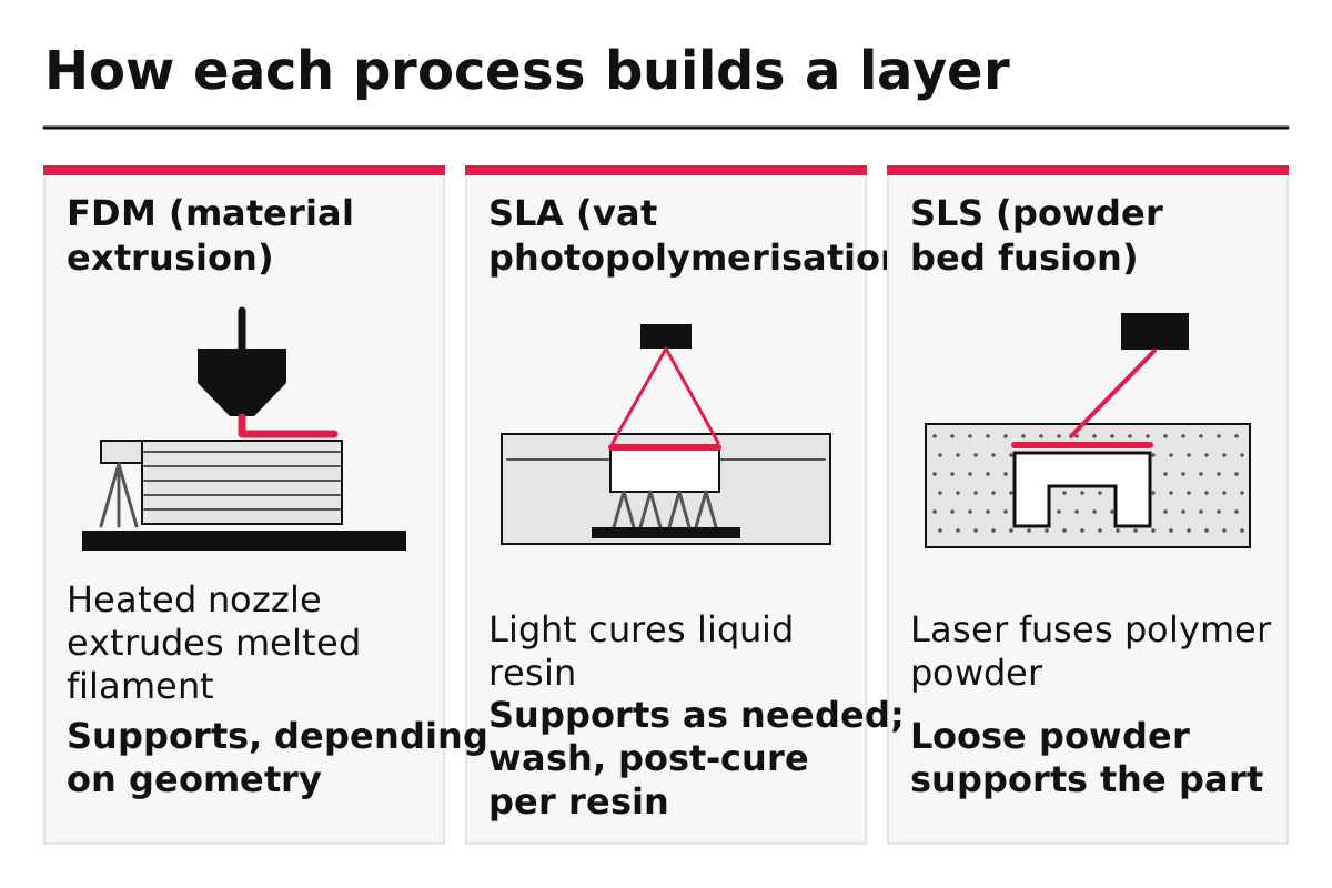
| FDM (fused deposition modelling) or FFF | Material extrusion | Plastic filament melted and drawn through a heated nozzle |
| SLA (stereolithography), including LCD/MSLA and DLP resin printers | Vat photopolymerisation | A light source curing liquid resin |
| SLS (selective laser sintering) | Powder bed fusion | A laser fusing polymer powder, with loose powder holding the part |
The category matters because it predicts the trade-offs: extrusion leaves visible road lines and weaker bonds between layers, resin curing gives fine detail and needs washing, and powder fusion supports itself but leaves a grainy surface.
Prototypes also leave the printer at some point. When a design needs metal, production plastic or tight tolerances, the comparison in 3D printing vs CNC machining for prototypes picks up where this guide stops.
Takeaway: Treat 3D printing as one route into rapid prototyping, and name the process category before you compare machines.
The 5-step print-test loop
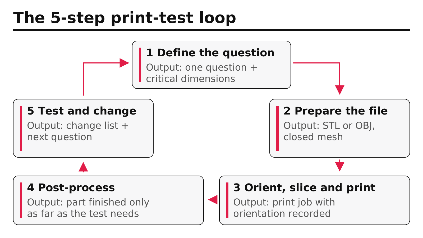
The loop has five steps: define what the model must prove, prepare the file, orient, slice and print, post-process only as far as the test needs, then test and change the design. Each round starts with a written question and ends with a change list; steps 2 to 4 follow the design, print and post-process workflow printer makers describe.
Step 1 — Write down what this model must prove
Write one sentence: “This print checks whether the grip fits a large hand” or “This print checks whether the lid snaps shut twice without cracking.” List the two or three dimensions that sentence depends on. Output: a question and a short list of critical dimensions.
Step 2 — Prepare the file
Model the part in CAD, then export a mesh. Formlabs describes the standard route as exporting an STL or OBJ file and loading it into print preparation or slicing software. Check that the mesh is closed, that walls are thicker than the printer’s minimum (see the quick specs) and that holes you plan to measure are modelled at their real size. Output: a printable file and a note of any features close to the limit.
Step 3 — Orient, slice and print
The slicer splits the model into layers and adds supports. Orientation is a design decision: on FDM, a clip printed so that its bending load runs across the layers is far more likely to snap. Keep critical surfaces away from supports if you intend to judge their finish. Output: a print job with orientation recorded, so the next round is comparable.
Common mistake: Changing orientation, material and design at the same time. If the next print behaves differently you will not know which change caused it.
Step 4 — Post-process to the level the question needs
Formlabs lists the basic jobs: removing any supports on FDM and SLA parts, washing SLA parts and post-curing them where the resin requires it, and removing loose powder and cleaning SLS parts. Beyond that, finish to what the test needs: light sanding for a handling test, priming and painting for an appearance review. If you sand a mating face, note it, so you do not mistake the adjusted fit for print accuracy. Output: a part finished just enough for its test.
Step 5 — Test, record and change the design
Run the test from step 1, measure the critical dimensions, and write down what you would change. Photograph the result next to the previous version; that record becomes the evidence of iteration you will later want in a design portfolio. Output: a change list and the question for the next loop.
Takeaway: Every loop starts with one written question and ends with one change list; the printer sits in the middle, not at the start.
FDM vs SLA vs SLS: how do the three methods compare for prototypes?
FDM, with what Formlabs calls low-cost consumer machines and materials, is usually the cheapest way to check shape and size, SLA is the choice when small details and surface quality decide the test, and SLS suits functional parts with clips, hinges or internal channels because the powder supports the part. The table compares them on the same dimensions; where a public source does not give a figure, it says so.
| Factor | FDM | SLA | SLS |
|---|---|---|---|
| Material form | Thermoplastic filament | Liquid photopolymer resin | Polymer powder, mostly nylon |
| Smallest wall (Formlabs figures) | About 0.8 mm | 0.2 mm on a Form 4 | 0.3 mm horizontal, 0.6 mm vertical on a Fuse 1+ 30W |
| Typical tolerance (Protolabs Network) | ±0.5 mm desktop, ±0.2 mm industrial | To be confirmed with your printer or service | ±0.3 mm |
| Supports | Depending on geometry and orientation; removed by hand or dissolved | Depending on geometry and orientation; removed after printing | Not needed; loose powder supports the part |
| Strength between layers | Weaker than along the extruded lines | Close to uniform, according to Formlabs | Mostly uniform, varies by powder, according to Formlabs |
| Surface straight off the machine | Visible layer lines | Smooth, fine detail | Slightly grainy, even across the part |
| Post-processing | Support removal, sanding | Wash, post-cure where the resin requires it, support removal | Powder removal, media blasting |
| Good first use in a prototype | Size, fit in the hand, rough layout | Appearance models, small buttons and text, clear parts | Snap fits, hinges, enclosures that get handled and dropped |
Two cautions on reading the table. First, the wall figures are for named Formlabs machines and the tolerances are a service’s typical values, so another printer may differ; confirm with a test coupon. Second, the strength row is about direction, not absolute strength: an FDM part can be strong along its lines and still split between layers.
If the answer you need is “how does the production part behave,” none of the three may be right. Machined plastic has the material’s full properties, which is why the CNC comparison recommends machining for some functional tests.
Takeaway: Pick FDM for shape, SLA for detail and finish, SLS for handling and snap tests, then confirm the limits on your own machine.
Which fidelity does each prototype stage need?
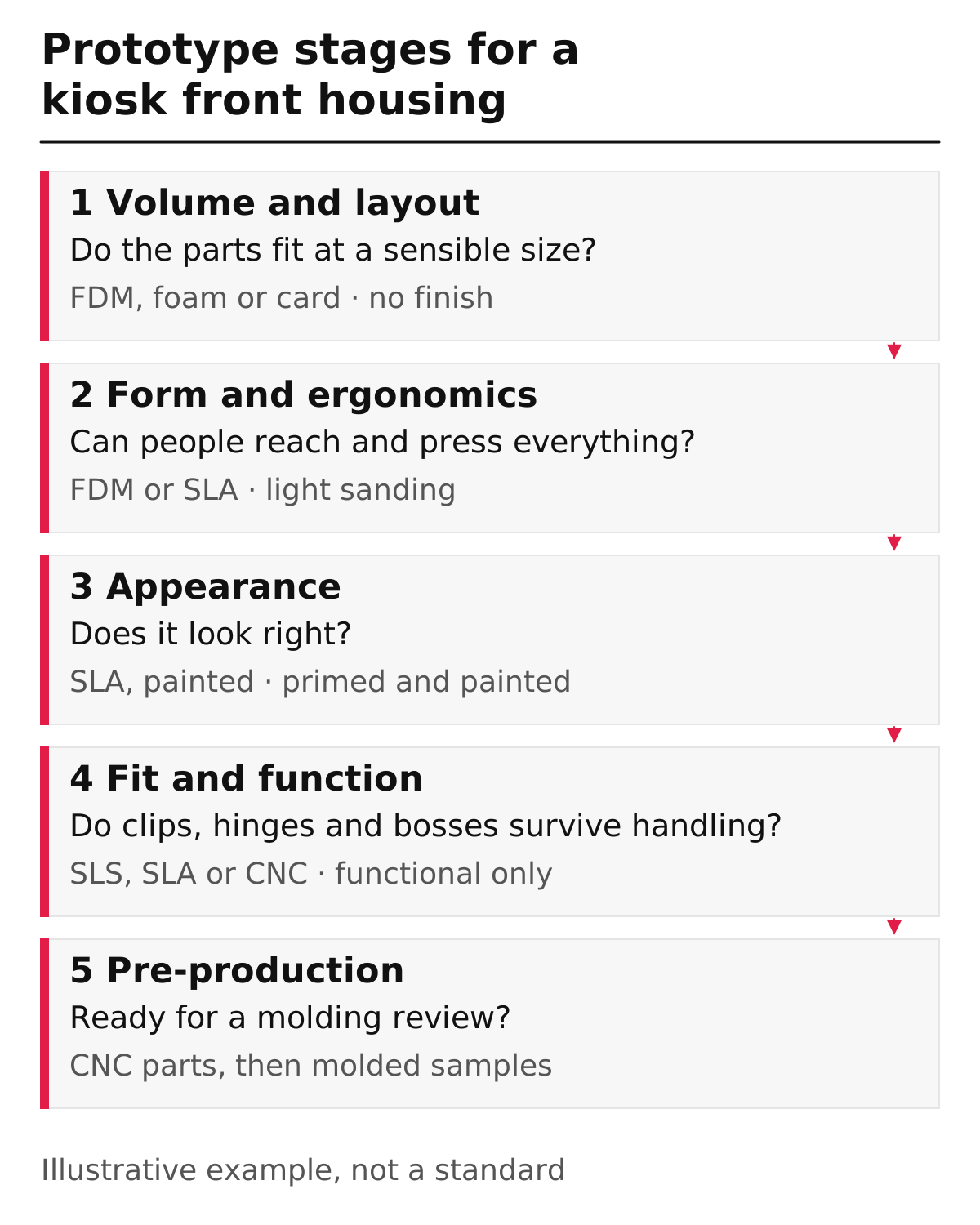
Match fidelity to the question: early models should be cheap and quick to throw away, and only the last rounds need production-like material and accuracy. The checklist below is our editorial guide for a typical plastic enclosure, using a self-service kiosk’s front housing as an illustrative example; it is not a standard and the stage names vary between teams.
| Stage | Question the model answers | Usual process | Finish level | Ready to move on when |
|---|---|---|---|---|
| 1. Volume and layout | Do the screen, card slot and buttons fit at a sensible size? | FDM, foam or card | None | Overall dimensions are agreed |
| 2. Form and ergonomics | Can people reach, read and press everything comfortably? | FDM or SLA | Light sanding | Users complete the main tasks without guidance |
| 3. Appearance | Does the part look right in colour, edges and surface? | SLA, painted | Primed and painted | Reviewers sign off the look |
| 4. Fit and function | Do clips, hinges and screw bosses work and survive handling? | SLS, SLA or CNC | Functional only | Assemblies close and reopen repeatedly without cracking |
| 5. Pre-production | Is the design ready for a molding review? | CNC parts, then molded samples | As specified | Drawings pass the injection molding design rules and the molder’s review; only molded samples confirm molded behaviour |
Published product announcements illustrate the kinds of question each stage asks; the mapping is our analogy, not a record of how these companies developed their products or whether they printed anything. ALPLA, for example, said it completed a pilot phase of its mono-material foam pump before planning production with anchor customers; the ALPLA foam pump reading looks at what such a design has to prove. In stage 2, an interface detail can be the whole question, as with the large actuator Aptar describes in its L’Occitane pump announcement. In stage 4, a shipping test can be the deciding check; Aptar says its Novus Advance pump passed its in-house ISTA-6 testing.
Common mistake: Judging a snap fit on a desktop FDM print. At about ±0.5 mm, the tolerance can be larger than the interference the snap depends on, so a failure may say more about the printer than the design.
Takeaway: Move up a stage only when the current model has answered its question; spending on finish too early slows the loop.
Which tools does the print-test loop need?
You need four kinds of tools: CAD to model, print preparation software to slice and orient, a printer or a print service, and finishing and measuring tools. Formlabs describes the software side as any CAD package or 3D scan, exported as STL or OBJ, then print preparation software that sets orientation and supports and slices the model into layers.
| Tool | What it does in the loop | What to check |
|---|---|---|
| CAD software | Holds the design you will change after each test | Parametric dimensions for the critical features from step 1 |
| Print preparation or slicer software | Orients, supports and slices the model | That orientation and settings are saved for the next round |
| Printer or print service | Builds the part | Process, material and published limits for walls and tolerance |
| Post-processing gear | Support cutters for FDM and SLA; wash and cure stations for SLA; powder removal for SLS | Safety guidance for resin and powder handling |
| Measuring tools | Calipers, a gauge or a reference part | That you measure the same features every round |
University makerspaces and online services remove the need to own a printer. Upload the same STL to a service, and the published tolerance and wall limits replace your own machine’s, which is useful when you need SLS or industrial FDM for one round only. Our prototyping articles collect the related guides.
Takeaway: Keep the CAD, the slicer settings and the measurements together; the loop only works if each round is comparable.
What drives the cost of a 3D printed prototype?
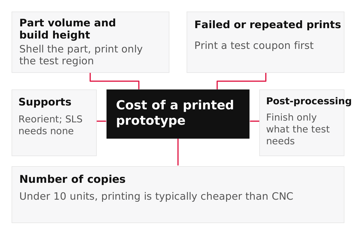
The cost of a printed prototype depends mostly on how much material and machine time the part needs, how much support and finishing it requires, and how many rounds you print. Protolabs notes that cost generally depends on quantity, how fast you need the parts, the material and the complexity of the geometry. We do not quote prices here because they change by printer, material and service.
| Cost driver | Why it adds cost | How to reduce it |
|---|---|---|
| Part volume and build height | More material and longer machine time | Hollow or shell the model; print only the region you are testing |
| Supports | Extra material on FDM and SLA, plus removal time | Reorient the part; SLS needs no supports |
| Post-processing | Washing, curing, sanding, painting take hands-on time | Finish only what the test needs |
| Failed or repeated prints | Material and time spent twice | Print a small test coupon of critical features first |
| Number of copies | No setup per design, but each copy adds material, machine time and finishing | Protolabs Network lists printing as typically cheaper than CNC under 10 units; batch copies in one build where you can |
| Speed | Faster turnaround from a service usually costs more | Batch several design variants into one order |
The cheapest round is often the one you do not print: if a cardboard or foam model answers the step 1 question, use it. When the part heads toward molding, costs start to depend on tooling decisions, which is why the wall thickness, rib and draft rules are worth applying before the last printed rounds. Every article on the 3D printing tag covers a related cost or process question.
Takeaway: Reduce material, supports and finishing before you look for a cheaper printer or service.
When this does not apply
The guidance above covers plastic prototypes in small numbers, built on common FDM, SLA and SLS equipment. It does not hold in these cases:
- Metal parts. Metal powder bed fusion and other metal processes have their own limits and costs; this guide does not cover them.
- Production behaviour. A printed part does not prove how a molded or machined part will behave. Confirm strength, heat resistance and tolerance in the production process.
- Higher quantities. Protolabs Network’s table moves plastic parts toward CNC at 100–1,000 pieces and toward injection molding beyond 1,000.
- Regulated products. Medical, food-contact or safety-critical parts are outside this guide; check the requirements that apply to the product’s use.
- Other machines. Wall and tolerance figures here belong to named printers and one service’s typical values. Print a test coupon on your own machine.
Takeaway: Use printed prototypes to learn quickly, and confirm anything that must hold in production with the production process.
How this page was put together
We compiled this guide on October 7, 2026 from public sources: Loughborough University’s Additive Manufacturing Research Group pages for the process categories, Formlabs’ comparison of FDM, SLA and SLS for wall limits and workflow, Protolabs Network’s comparison of 3D printing and CNC machining for tolerances and quantity guidance, and a 2023 Protolabs article for history and cost factors. Formlabs makes SLA and SLS printers, and Protolabs and Protolabs Network sell printing and machining, so their figures are presented as their statements, tied to the machines or services they describe. The stage checklist and the kiosk housing example are our editorial guidance, not test results. Nothing on this page comes from our own printing.
Related reading:
- 3D printing vs CNC machining for prototypes — Decide when a prototype should be machined instead of printed.
- Injection molding design rules — Check walls, ribs and draft before the last printed round.
- Industrial design portfolio guide — Turn your print-test records into portfolio pages.