Rapid prototyping is the group of techniques used to quickly fabricate a physical part or assembly from a three-dimensional design, iterating several times between digital designs and physical prototypes with a quick and cost-effective workflow.
Rapid prototyping is a common early step within the product development process during which design teams quickly iterate an initial model—often a minimum viable product (MVP)—using injection molding with comparatively inexpensive aluminum molds, 3D printing, CNC machining, or sheet metal fabrication.
Early prototypes should be simple, quick, cheap, and incomplete, and the most common mistake novice prototypers often make is attempting to build the end-to-end concept or system from the beginning rather than progressively building and testing from single parts by building only what is necessary to address one or two narrow questions at a time.
Work through the process definitions, early failure modes, fidelity categories, stage-gate boundaries, and qualifying questions below before building your next physical model.
What is rapid prototyping? Rapid prototyping meaning and definition
In rapid prototyping vs 3D printing terminology, as rapid prototypes are usually constructed using additive fabrication techniques as opposed to traditional subtractive methods, the phrase has become synonymous with additive manufacturing and 3D printing.
Although media likes to use the term “3D Printing” as a synonym for all Additive Manufacturing processes, in 2010 the American Society for Testing and Materials (ASTM) group “ASTM F42 – Additive Manufacturing” formulated a set of standards that classify the range of Additive Manufacturing processes into 7 categories (Standard Terminology for Additive Manufacturing Technologies, 2012).
US Patent US4575330A for “Apparatus for production of three-dimensional objects by stereolithography” by inventor Charles W. Hull (application number US06/638,905) was filed on 1984-08-08 and published on 1986-03-11.
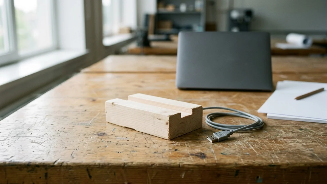
In the prototyping context, “tool” refers to physical equipment while “process” refers to an action that the tool accomplishes, and approaching every physical prototyping task with the use of a 3D printer confuses tool with process when laser cutting mating parts for assembly or connecting pieces of stock via fastening hardware are other effective processes.
When your design question fits an additive print loop, follow our companion guide on rapid prototyping with additive printing processes to prepare and run the build cycle.
Progressive prototyping sequences and iteration cost escalation
Start with paper sketches and simple benchtop mockups before committing hours to computer-aided modeling or ordering custom fabricated parts.
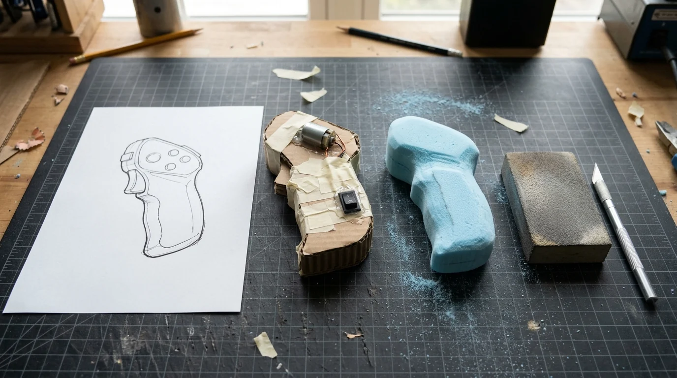
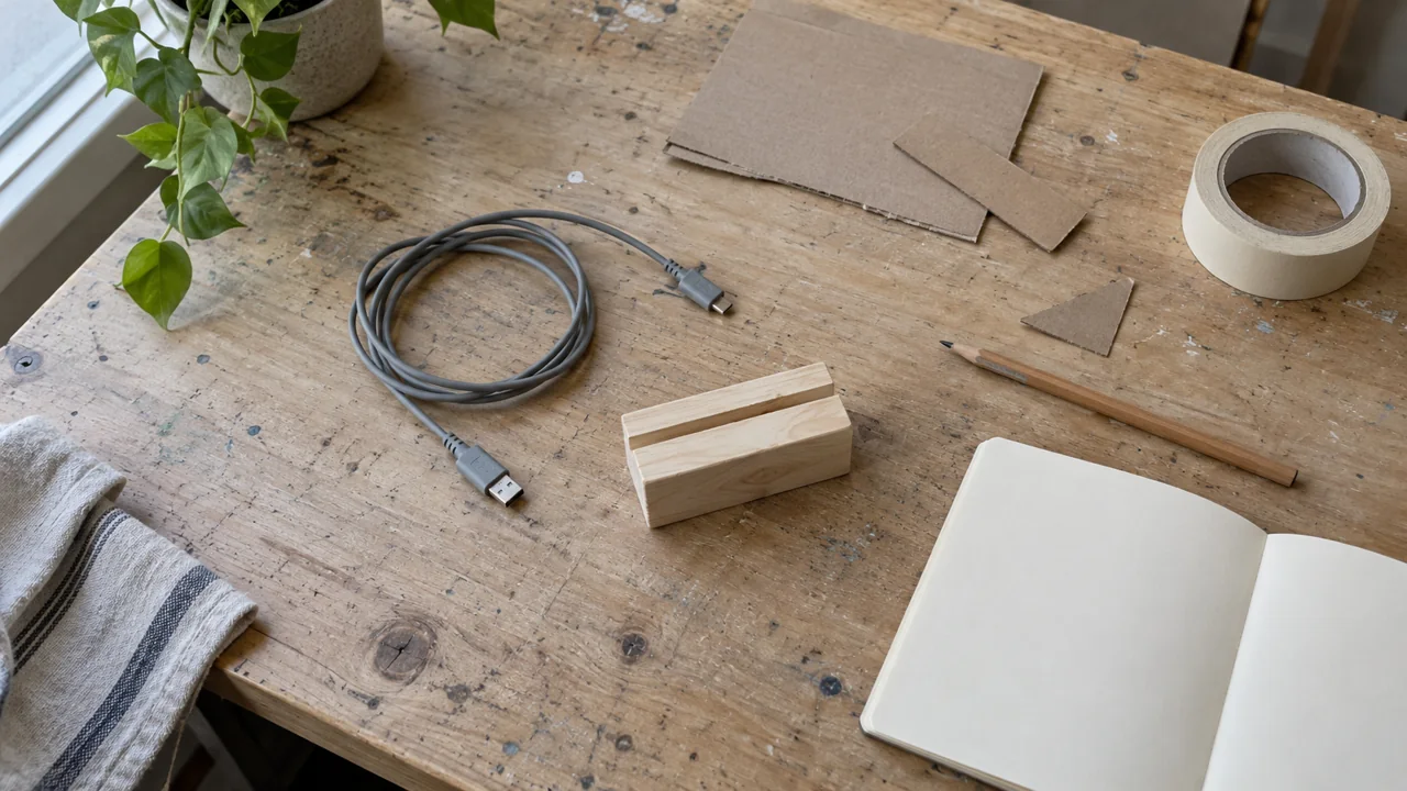
When making an assembly with some off-the-shelf components and a novel 3D-printed part, the first step is not to buy all of the parts and head straight to the 3D printer: the first versions should be hand-drawn sketches, followed by a model with a combination of cardboard, tape, and a subset of available components, before proceeding to a CAD model.
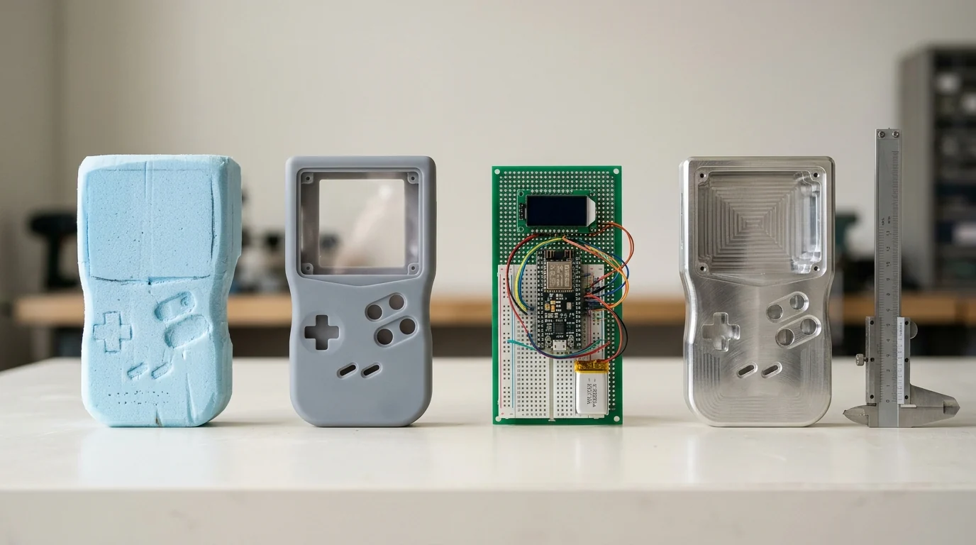
A handmade foam Concept Model to explore form is chosen for speed when 3D data is not available.
Jumping right into 3D CAD modeling without sketching is a common mistake when cardboard, foam stock, and sticky tape are acceptable materials for a benchtop model, and freelance CAD designers typically charge $20-50+ per hour.
Solid models, such as STEP files, can be interpreted by all manufacturing processes whereas mesh files like STL models can only be used for 3D printing.
Sketches and foam models done by a designer at the beginning of development will cost a company $50 in materials, a more refined rapid prototype based on 3D prints, buy-in parts, and a vacuum cast overmold might set the company back somewhere in the order of $500-$1,000, and tooling changes in the production phase may lead up to $50,000 in total cost.
It took the IDEO design team 80 foam models just to get the shape of the first ergonomic computer mouse right for Microsoft back in 1987, and it took 5,127 prototypes for James Dyson to develop the first “cyclone technology” vacuum cleaner over the course of 15 years.
Plan your material and workshop spending across rounds with our prototype budget worksheet.
Rapid prototyping and engineering models: looks-like, feels-like, works-like, and is-like fidelity
There are four primary categories of prototypes organized from least to most burdensome: Looks-like, Feels-like, Works-like, and Is-like.
Focused prototypes are meant to embody only a part of the product’s requirements—and can be a “looks-like” model, a functional “works-like” model, or one that demonstrates partial form and function in order to test certain sub-functionalities—whereas when a prototype incorporates all requirements and functionalities with the design, it is called the engineering prototype.
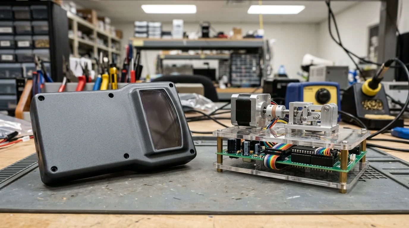
Concept models and subsystem breadboards
Concept Models have the purpose to study scale, develop form, and explore ergonomics from sketches, verbal description, or 3D data, using hand-built foam (insulation or urethane), foam core, clay, cannibalized existing products, rapid prototyping (Z Corp, SLS, SLA), or machining from block, tube, and sheet stock, with tolerances marked “Not important” and a quantity of “Usually ONE”.
An experimental subsystem setup is sometimes called a “breadboard” after the practice, in the early days of radio, of building the circuit up on a wooden board; for a mechanical linkage, if linkage dynamics are important an accurate breadboard would be necessary, whereas if only kinematics are required a Lego model or even cardboard model might be sufficient.
Looks-like and feels-like prototypes
Looks-like prototypes represent the final product at an abstract level but may lack many of its functional aspects; ergonomics, user interfaces, and overall user experience can be validated with looks-like prototypes, usually starting with sketches, foam or clay models, then moving into CAD modeling; as the design is finalized, create looks-like prototypes using the actual colors, materials, and finishes (CMF).
Feels-like prototypes support evaluation of the weight, balance, or size of a concept; in the Novonate case study (Figure 3), a prototype had a more accurate 3D shape than other models and had the right durometer (stiffness), but it was entirely opaque due to limitations with the 3D printing material, and NICU nurses had a hard time evaluating the feel of the device without getting distracted by the fact that it was not see-through.
Works-like, non-form-factor, and combined models
Parallel to the industrial design process, engineering teams work on another set of prototypes to test, iterate, and refine the mechanical, electrical, and thermal systems that make up the product, often developing and testing these critical core functions in separate sub-units before integrating them into a single product prototype so the subsystem approach isolates variables.
A works-like prototype does not need to be fully functional—most works-like prototypes barely work, and they might only work in one specific way and under limited conditions—and attempting to make a prototype achieve looks-like, feels-like, and works-like goals simultaneously can over-constrain the building or testing processes.
Non-form-factor (NFF) models are essentially giant versions of the product design meant to house placeholder versions of all functional components in order to develop a working demonstrator, with rudimentary working versions of the electronics included in the form of hardware development kits, Arduino, or Raspberry Pi constructions.
A Looks Like Model (LL Model) has an aesthetic purpose and shows surface finish, color, clear parts, labels, and tactile materials, whereas a Looks Like/Work Like Model (LL/WL) has the same purpose including functional requirements—with materials used to replicate production material performance and batteries, electronics, springs, and LEDs—at tolerances “tight as needed” and a quantity of 1-12.
Engineering Models have the purpose to confirm geometry, test production materials, and review function from 3D data and detailed part drawings, using rapid prototyping (SLS, FDM, SLA), CNC or machined production materials, or prototype molds in production materials, with critical tolerances and a quantity of usually ONE.
Prototype model comparison table
| Model type | Purpose and inputs | Processes and materials | Tolerances and quantity |
|---|---|---|---|
| Concept Models | Concept Models purpose: study scale, develop form, explore ergonomics from sketches, verbal description, or 3D data. | Concept Models processes and materials: hand build (foam, insulation or urethane, foam core, clay, cannibalize existing products), rapid prototyping (Z Corp, SLS, SLA), and machining (block, tube and sheet stock). | Concept Models tolerances: Not important; quantity: Usually ONE. |
| Looks Like / Work Like (LL/WL) | Looks Like/Work Like Model (LL/WL) purpose: aesthetic surface finish (color, clear parts, labels, tactile materials) including functional requirements. | Looks Like/Work Like Model (LL/WL) materials: materials used to replicate production material performance, including batteries, electronics, springs, and LEDs. | Looks Like/Work Like Model (LL/WL) tolerances: tight as needed; quantity: 1-12. |
| Engineering Models | Engineering Models purpose: confirm geometry, test production materials, and review function from 3D data and detailed part drawings. | Engineering Models processes and materials: rapid prototyping (SLS, FDM, SLA), CNC or machined production materials, and prototype molds in production materials. | Engineering Models tolerances: critical; quantity: usually ONE. |
Hardware validation gates: engineering, design, and production validation
In the Engineering Validation Test (EVT) stage, an engineering-level “beta” prototype is developed as a minimum viable version of the final commercial product that is designed for manufacturing (DFM), used for lab-based user testing with a select group of lead users, communicating production intent to tooling specialists, and performing power, thermal, and EMI tests.
In the EVT phase, approximately 20 to 50 units (and <50 over a 3-6 months duration) are produced using high-precision processes such as additive manufacturing and CNC machining, or a series of casts based on soft tooling such as silicone or 3D printed molds.
Urethane Castings using Silicone RTV Molds and cast urethane resins are used for sales samples and LL/WL models in quantities of 10 - <50 with delivery of 1-2 weeks, whereas Prototype Tooling in Aluminum or Pre-hardened Steel (machined, EDM) has a tool life of 12 - 250,000 and delivery of 4-6 weeks.
In the Design Validation Test (DVT) stage, the contract manufacturer develops the first hard tool for every made part, and aluminum molds may be used to optimize the design, and while typically 50 to 200 units are produced (or over 1,000 units for large projects), units undergo environmental chamber tests, thermal cycles, vibration, ESD, biocompatibility, chemical resistance, certifications such as FDA, FCC, UL, CE, EC, and RoHS, aging, radiation, cosmetic, wear, and drop tests.
The Production Validation Test (PVT) is the final phase before mass production starts: hard tooling is fixed so no more changes to either the product design or production molds can be made, a typical outcome of the PVT stage is 500+ units or at least 5% of the first production run quantity, and mass production (MP) typically starts at a minimum quantity of 5,000 units.
In Stage-Gate International’s model, Stage 3 (Development) has as its main deliverable a fully functioning prototype (or equivalent) ready for customer and field testing, while Stage 4 (Testing and Validation) typically includes beta tests, user pilots, field trials, extended lab testing, and trial production runs.
NASA’s Verification and Validation Plan Outline identifies activities that establish compliance with the requirements (verification) and establish that the system will meet the customers’ expectations (validation), with Section 5.2 (Test Articles) covering descriptions of breadboards, prototypes, engineering units, qualification units, protoflight units, and flight units.
Coordinate your gate entrance and exit criteria with our guide to product design stage-gate milestones.
When additive printing is not enough for a prototype
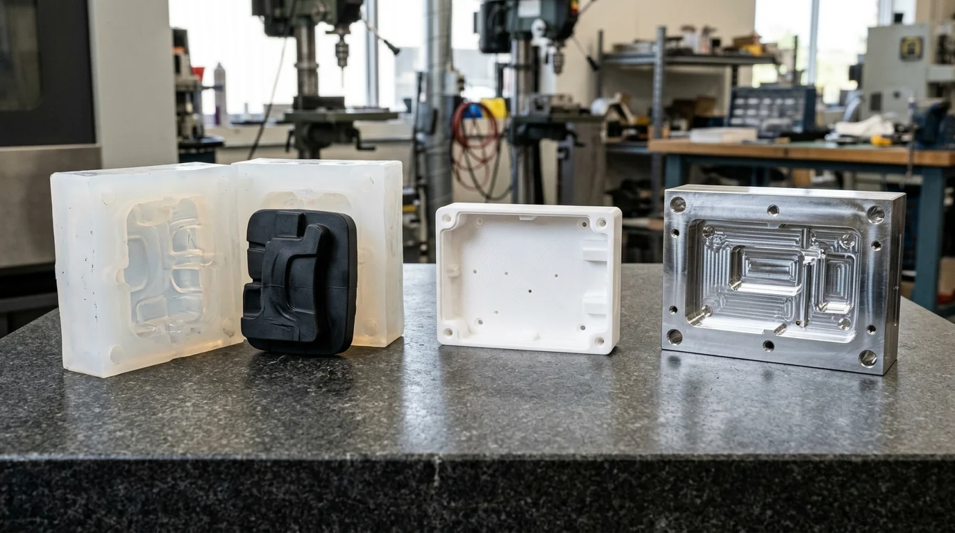
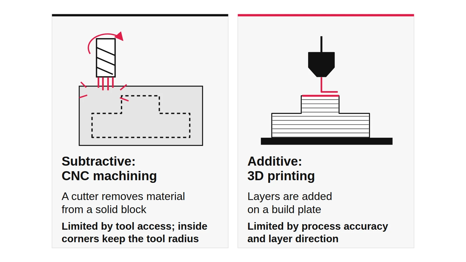
In CNC machining, a solid block (or rod stock) of plastic or metal is clamped into a CNC mill or lathe respectively and cut into a finished part through a subtractive process, giving the part the complete, homogenous properties of the plastic because it is made from solid blocks of extruded or compression molded thermoplastic resin, as opposed to most additive processes, which use plastic-like materials.
Parts made using SLA have limited use for functional testing and should be used with minimal UV and humidity exposure so they do not degrade, while PolyJet parts have limited strength (comparable to SLA), are not suitable for functional testing, give no insight into the eventual manufacturability of the design, and have colors that can yellow when exposed to light over time.
In urethane casting (vacuum casting), liquid polyurethane resins are poured into a silicone mold; the molds can wear out after a limited number of uses, and these resins are thermosets rather than true thermoplastics, so their performance envelope is narrower and they generally lack the same long-term durability, high-temperature resistance, and fatigue strength as injection-molded parts.
At the gross level, assembly and fit testing checks for design errors such as placing two tabs at 2 in. (50.8mm) spacing and the mating slots at 1 in. (25.4mm) spacing, whereas at the fine level it is a matter of minor dimensional differences and tolerances, so any test involving tolerances needs to use the actual manufacturing process or one which has similar tolerances.
During prototyping, designers should not box themselves into a corner with fancy geometries that print beautifully but cannot be replicated via injection molding, which requires specific design methods such as uniform wall thickness and draft angles, and even the same material can act differently when printed versus molded.
3D printing can deliver prototypes within 24 hours and additive manufacturing is typically more affordable than CNC for quantities under 10 units, whereas for high-volume production of hundreds to thousands of parts, often, injection molding or other traditional forming technologies offer the best economies of scale.
The minimum resolution of most laser cutters is ~1mm, which can rule out attempting to create a cut with ~10 micron thickness, and attempting to drill a simple hole in a plastic 3D printed or laser-cut part using a drill press or hand drill generates heat that quickly melts small plastic chips.
Process accuracy, wall thickness, and part-size comparison
| Technology | Tolerance | Minimum wall thickness | Maximum part size |
|---|---|---|---|
| CNC machining | ± 0.025 - 0.125 mm. | 0.75 mm. | Milling 2000 x 800 x 1000 mm; Lathe Ø 500 mm. |
| SLS | ± 0.300 mm. | 0.7 - 1.0 mm. | 300 x 300 x 300 mm. |
| FDM | Desktop ± 0.500 mm; Industrial ± 0.200 mm. | 0.8 - 1.0 mm. | Desktop 200 x 200 x 200 mm; Industrial 900 x 600 x 900 mm. |
| SLM/DMLS | ± 0.100 mm. | 0.40 mm. | 230 x 150 x 150 mm. |
| Binder jetting | ± 0.200 mm. | 2.0 mm. | 380 x 355 x 735 mm. |
For prototyping a plastic electronics enclosure, Protolabs Network compares CNC machining (cost $$, common materials ABS and Nylon, lead time 1-2 weeks, accuracy ± 0.125 mm), Desktop FDM (cost $, common materials PLA, ABS, and Nylon, lead time 1-3 days, accuracy ± 0.500 mm), and SLS (cost $$, common material Nylon, lead time less than a week, accuracy ± 0.300 mm).
Compare subtractive and additive trade-offs in our guide on choosing between additive printing and machining for prototypes, and check wall and draft rules in injection molding design rules.
Qualifying your prototyping needs and documenting each build
Qualifying your prototyping needs requires answering what type of model you need, what type of input you have (sketches, control drawings, or 3D data), whether the production material is required, what the tolerances are, how many you need, when you need it, and whether you are working within a budget.
IDEO.org’s Prototyping Plan Template recommends completing the planning activity several days before embarking on testing, blocking 1 hour to complete the whole plan and facilitation guide, aiming for 2-3 overarching learning questions with more detailed questions nested within those, and role-playing a few practice interviews or testing sessions before going out to the community.
Skipping documentation in the name of efficiency is a common error; for mechanical builds, a few simple annotated photographs with relevant arrows, a good caption, and a parts/materials list paired with a CAD image and a link can be effective, while for electronics builds the circuit diagram (with labeled parts/values) is essential, and software builds require revision control and in-line comments.
Organize your test sessions with our physical prototype testing plan, define testable inputs in design brief versus design specification, or browse all industrial design and prototyping articles for the next stage of your project.
Questions to resolve before starting a prototype build
How do in-house resin printing and outsourcing compare on a single prototype?
In Formlabs’ Black Diamond Equipment avalanche shovel prototype comparison, printing on a Form 4 L with Grey Resin took 8 hours and cost $45, compared to 7 days and $1000 for outsourcing.
Can additive prototypes handle functional field environments?
Diving camera manufacturer Paralenz used 3D printing to create functional prototypes that endured testing 200+ meters below sea level.
How do print speeds compare across desktop filament, resin, and powder printers?
In Formlabs’ gaming controller print speed comparison for 1 assembly (3 parts), an FDM 3D printer (Bambu Lab X1, PLA Basic, 120 microns layer height, 15% infill density) took 10 h 32 min, an SLA 3D printer (Form 4, Grey Resin, 100 microns layer height) took 2 h 36 m, and an SLS 3D printer (Fuse 1+ 30W, Nylon 12 Powder, 110 microns layer height) took 3 h 52 min printing plus 6 h 52 min cooling.
What are the equipment price ranges for prototyping machines?
Budget FDM printers and 3D printer kits start at around $200, professional desktop FDM printers range from $2,000 to $8,000, industrial FDM systems are available from $15,000, low-cost resin 3D printers are available for $200 to $1000, professional SLA 3D printers are in the $2,500 to $10,000 range, large-format resin printers are in the $5,000 to $25,000 range, benchtop industrial SLS starts under $30,000 ($60,000 ecosystem), and traditional industrial SLS starts at around $200,000.
Sources
- Formlabs — What is Rapid Prototyping? Methods, Tools and Examples
- Protolabs — Selecting a Rapid Prototyping Process
- Stanford Biodesign — Prototyping: Build
- Loughborough University Additive Manufacturing Research Group — Categories of Additive Manufacturing
- Google Patents — Apparatus for Production of Objects by Stereolithography (Charles W. Hull)
- MIT OpenCourseWare — Product Design and Development: Prototyping Overview
- Xometry — Product Development Guide: Rapid Prototyping
- Formlabs — Validation Testing in Product Development: From POC to EVT, DVT, PVT, and Mass Production
- MIT OpenCourseWare — Design Packet: Implementation
- Stage-Gate International — The Stage-Gate Model: An Overview
- NASA — Appendix I: Verification and Validation Plan Outline
- Fictiv — Rapid Prototyping: A Guide on the Methods for Fast Product Development
- Protolabs Network (Hubs) — Additive Printing and CNC Machining Guide
- IDEO.org Design Kit — Prototyping Plan Template