Engineering kiosk enclosures for retail, transit ticketing, hospital check-in, and outdoor drive-thru lanes requires coordinating sheet metal enclosure DFM, forced-air thermal cooling, ingress/impact sealing, and front-service ergonomics in one chassis. Specifying the wrong aluminum temper, placing PEM holes inside press-brake bend zones, or sizing fans from zero-pressure free-air ratings causes cracked flanges, ovalized fastener bores, LCD thermal blackening, and costly field rework.
Unlike high-volume plastic housings governed by injection moulding design guidelines for wall thickness, rib ratios, and draft, interactive kiosks ship in batches of 1 to 500+ units where laser cutting and press-brake forming avoid hard-tooling investment. Below are the engineering lookup tables and reference equations for sheet metal gauge selection, flat-pattern bend relief math, PEM hardware and UL 2361 powder-coat masking, static-pressure-derated fan sizing, NEMA 250 / IEC 62262 IK10 sealing, 2010 ADA §308 / §707 reach compliance, and 3D printing vs CNC machining sub-assembly allocation.
Quick engineering specification summary
| Subsystem parameter | Quantitative design rule | Standard / source | Dominant failure mode if violated |
|---|---|---|---|
| Sheet alloy & gauge | 14–16 ga (1.52–1.90 mm) CRS or 304/316L SS; 2.0–3.0 mm 5052-H32 Al (10–12 ga base) |
ASTM A1008 / Protolabs | Panel deflection (< 16 ga); outer-grain fracture if 6061-T6 is brake-formed |
| Inside bend radius | Uniform R_min ≥ 1.0T (1.0–1.5T on 304/316L SS; K ≈ 0.40–0.44) |
Protolabs & Xometry | Tensile micro-cracking (R < 0.8T) and extra press-brake setup charges |
| Flange & hole relief | Flange L_min ≥ 4T + R; hole-to-bend ≥ 2.5T + R; corner notch W ≥ 1.0T, D ≥ T + R + 0.5 mm |
Protolabs & Xometry | Short flange drops into V-die; holes stretch into ovals; corner intersections tear |
| Clinch hardware | Hole +0.08 / -0.00 mm (no chamfer); C_min = 4.8–8.6 mm (M3–M6); blind BSO on skins |
PennEngineering PEM | Fastener spin-out or edge bulge if C < C_min or punch-side hole is chamfered |
| Powder-coat masking | 50–100 µm per side; plug threads; mask Ø15–20 mm bare pad at PE studs (R < 0.1 Ω) |
UL 2361 & IEC 62368-1 | Seized bolts; door binding; failed ground-bond test (> 10^9 Ω paint insulation) |
| Thermal chimney | V_CFM = (3.16 × Q_W) / ΔT_°F; derate free-air fan 35%–55% for ΔP = 25–75 Pa filter drop |
Pfannenberg Guide | Isotropic LCD blackening (> 65°C–70°C clearing) from hot air recirculation |
| NEMA & IK10 sealing | EPDM gasket compressed 25%–40% (6.4 mm latch pull); 4–6 mm glass on 10–15 mm gasket |
NEMA 250 & IEC 62262 | Hose-down leak (< 15% crush); gasket set (> 50%); tempered glass edge shatter |
| ADA & service access | Controls 15–48 in. (380–1,220 mm) AFF; 95°–120° door swing; 200–300 mm printer slide |
2010 ADA §308 / §707 | Non-compliant wheelchair reach (> 48 in.); sheared harness at hinge pinch gap |
1. Sheet Metal Enclosure DFM: Alloy Selection, Press-Brake Geometry, and PEM Hardware
Kiosk cabinets rely on CNC laser cutting and press-brake air bending because sheet metal delivers high stiffness, EMI shielding, and vandal resistance with zero mold NRE across 1 to 1,000+ units. Translating a concept from a design brief and testable specification into production sheet metal requires matching alloy ductility, bend reliefs, and self-clinching fastener tolerances to standard press-brake V-dies.
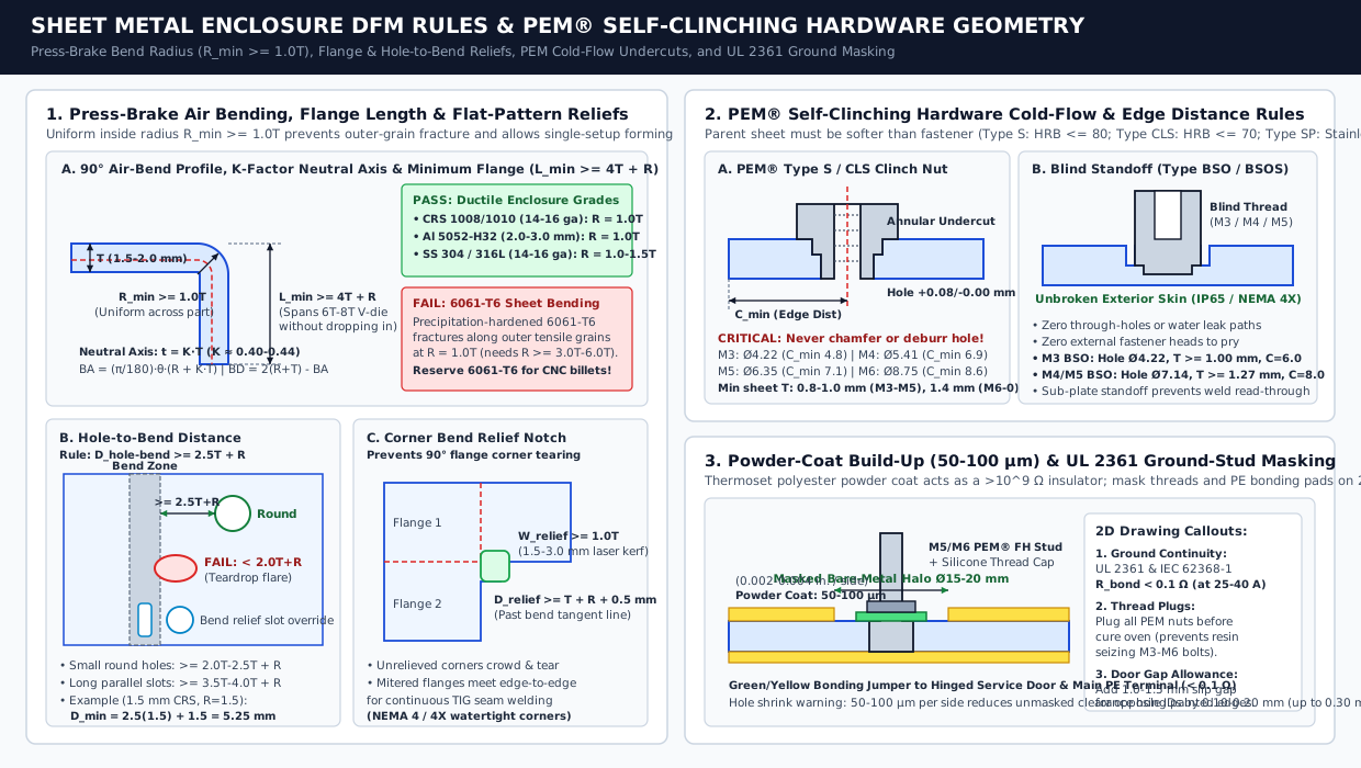
Enclosure Alloy and Sheet Gauge Lookup Table
| Alloy & grade | Kiosk thickness (gauge / mm) |
Modulus & yield | Min radius (R_min) |
Finish & corrosion rule | Primary kiosk application |
|---|---|---|---|---|---|
| CRS 1008 / 1010 (ASTM A1008) | 14–16 ga (1.90–1.52 mm) body/doors; 10–12 ga (3.42–2.66 mm) baseplate |
E = 200 GPa; σ_y ≈ 195–240 MPa |
1.0T (0.8T–1.0T across grain) |
Phosphate wash + 60–100 µm powder coat (or A60 galvanneal) |
Indoor retail, QSR, and lobby pedestals (45–80 kg mass resists tipping) |
| Aluminum 5052-H32 (Al-Mg) | 0.080–0.125 in. (2.0–3.0 mm) skins and internal thermal baffles |
E = 70.3 GPa (~1/3 steel stiffness); σ_y ≈ 193 MPa |
1.0T (Never brake-form 6061-T6, which cracks unless R ≥ 3.0T–6.0T) |
Chromate (MIL-DTL-5541) + powder coat or anodize |
Wall-mounted kiosks, transit housings, and solar skins (k ≈ 138 W/m·K) |
| Stainless 304 / 316L | 16 ga (1.52 mm) to 14 ga (1.90 mm) exterior skins and doors |
E = 193 GPa; σ_y ≈ 205–290 MPa (2°–4° springback) |
1.0T–1.5T |
304 SS ("#4" brushed) for food/outdoor; 316L (2%–3% Mo) for NEMA 4X coastal |
Outdoor ticketing, marine terminals, drive-thru lanes, and hospital kiosks |
Press-Brake Air Bending Rules and Flat-Pattern Bend Deduction Math
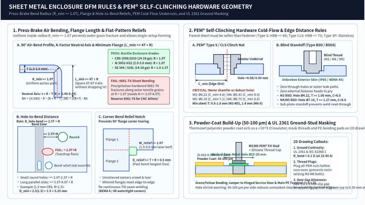
In air bending over a standard V = 6T to 8T bottom die, enforce four geometric rules in CAD:
- Uniform Inside Bend Radius (
R_min ≥ 1.0T): Keep one inside radius (R = 1.5 mmon16-gaCRS orR = 2.0 mmon2.0 mm5052-H32) across all bends so the part forms in a single press-brake setup. - Minimum Straight Flange Length (
L_min ≥ 4T + R): Short flanges drop into the V-die throat before stroke completion. Keep outside flange lengthL_min ≥ 4T + R(minimum3.0T + Rin ductile aluminum and3.5T–4.0T + Rin steel; forT = 1.52 mm,R = 1.52 mm,L_min ≥ 7.6 mm). - Hole-to-Bend Relief (
D_hole-bend ≥ 2.5T + R): Holes cut inside the bend deformation zone stretch into teardrop ovals (“hole flare”). Keep hole edges≥ 2.5T + Rfrom the inside bend tangent line (≥ 3.5T–4.0T + Rfor parallel slots), or add a relief cut along the bend line. - Corner Bend Relief Notches (
W_relief ≥ 1.0T,D_relief ≥ T + R + 0.5 mm): Where two90°flanges meet at a corner, cut a laser relief notch≥ 1.0Twide (1.5–3.0 mm) and≥ T + R + 0.5 mmdeep past the tangent lines to prevent tearing and align edges for TIG welding.
The K-factor (K = t_neutral / T ≈ 0.40–0.44 for 90° air bending) defines the neutral axis location used to calculate flat-pattern bend allowance (BA) and bend deduction (BD):
Flat-Pattern Bend Equations (Reference Engineering Example — Verify with Fabricator Die Library):
  Bend Allowance:   BA = (pi / 180°) × theta × (R + K × T)
  Outside Setback:  OSSB = tan(theta / 2) × (R + T)   [Equals R + T for a 90° bend]
  Bend Deduction:   BD = 2 × OSSB - BA                [Flat Length L_flat = L_leg1 + L_leg2 - BD]

Worked Example (16-ga CRS Kiosk Door Return Flange, T = 1.52 mm, R = 1.52 mm, theta = 90°, K = 0.42):
  BA = 1.5708 × (1.52 + 0.42 × 1.52) = 3.39 mm  |  2 × OSSB = 6.08 mm  ->  BD = 6.08 - 3.39 = 2.69 mm per bend.
Self-Clinching PEM Hardware and UL 2361 Powder-Coat Masking
Cut threads in 1.5–2.0 mm sheet strip after one to two pitches. Press self-clinching hardware (PennEngineering PEM Bulletin CL & SO) into laser-cut holes (+0.08 / -0.00 mm). Parent metal hardness must remain below fastener hardness (Type S for HRB ≤ 80; Type CLS stainless for HRB ≤ 70; Type SP for stainless steel up to HRB 88–90). Never chamfer or deburr the punch side of the hole, or sheet metal cannot cold-flow into the annular undercut:
| PEM fastener & thread | Min sheet T_min |
Hole (+0.08 / -0.00 mm) |
Min edge dist C_min |
Kiosk sub-assembly role |
|---|---|---|---|---|
Type S / CLS Nut — M3 × 0.5 |
0.80 mm (-0), 1.00 mm (-1) |
4.22 mm (0.166 in.) |
4.80 mm |
NFC/RFID readers, sensors, and cable clamps |
Type S / CLS Nut — M4 × 0.7 |
0.80 mm (-0), 1.00 mm (-1) |
5.41 mm (0.213 in.) |
6.90 mm |
Industrial PC (IPC) brackets, PSUs, and scanner plates |
Type S / CLS Nut — M5 × 0.8 |
0.80 mm (-0), 1.00 mm (-1) |
6.35 mm (0.250 in.) |
7.10 mm |
VESA 100×100 / 200×200 displays and printer slide rails |
Type S / CLS Nut — M6 × 1.0 |
1.00 mm (-00), 1.40 mm (-0/-1) |
8.75 mm (0.344 in.) |
8.60 mm |
Heavy concealed door hinges, gas struts, and sub-plates |
Type SO / SOS Standoff — M3 |
1.00 mm (0.040 in.) |
4.22 mm (M3) / 5.41 mm (3.5M3) |
6.00 / 6.80 mm |
Elevating controller PCBs off internal galvanized sub-plates |
Type BSO Blind Standoff — M4/M5 |
1.27 mm (0.050 in.) |
7.14 mm (0.281 in.) |
8.00 mm |
Exterior skins: zero visible holes, water paths, or pry points |
Thermoset powder coat adds 50–100 µm (2–4 mil) per face, reducing hole diameters by 0.10–0.20 mm and acting as an electrical insulator (> 10^9 Ω). On your 2D manufacturing drawings (see our manufacturing specification handoff checklist), call out: (1) silicone plugs in all PEM threads; (2) 1.0–1.5 mm nominal door-to-frame paint gap; and (3) a Ø15–20 mm bare-metal masked halo around every M5/M6 PEM Type FH protective-earth (PE) ground stud so green/yellow bonding jumpers achieve < 0.1 Ω continuity (25–40 A test) per UL 2361 and IEC 62368-1.
Takeaway: Use 14–16 ga CRS, 304/316L SS, or 2.0–3.0 mm 5052-H32 Al (never 6061-T6) with uniform R_min ≥ 1.0T bends, keep holes ≥ 2.5T + R from bends, specify blind BSO standoffs on exterior faces, and mask Ø15–20 mm bare pads around PE ground studs for < 0.1 Ω continuity.
2. Thermal Management, Derated Fan CFM Sizing, and NEMA / IK10 Sealing
Interactive kiosks house concentrated heat loads inside a vertical column: LCD backlights (25–45 W indoor 350–500 nit; 80–180 W outdoor 1,500–2,500 nit), solar irradiance (Q_solar = 600–1,000 W/m² adding 100–250+ W), the IPC (25–65 W), AC/DC power supplies (15–30 W), and receipt printer/scanner bursts (10–25 W).
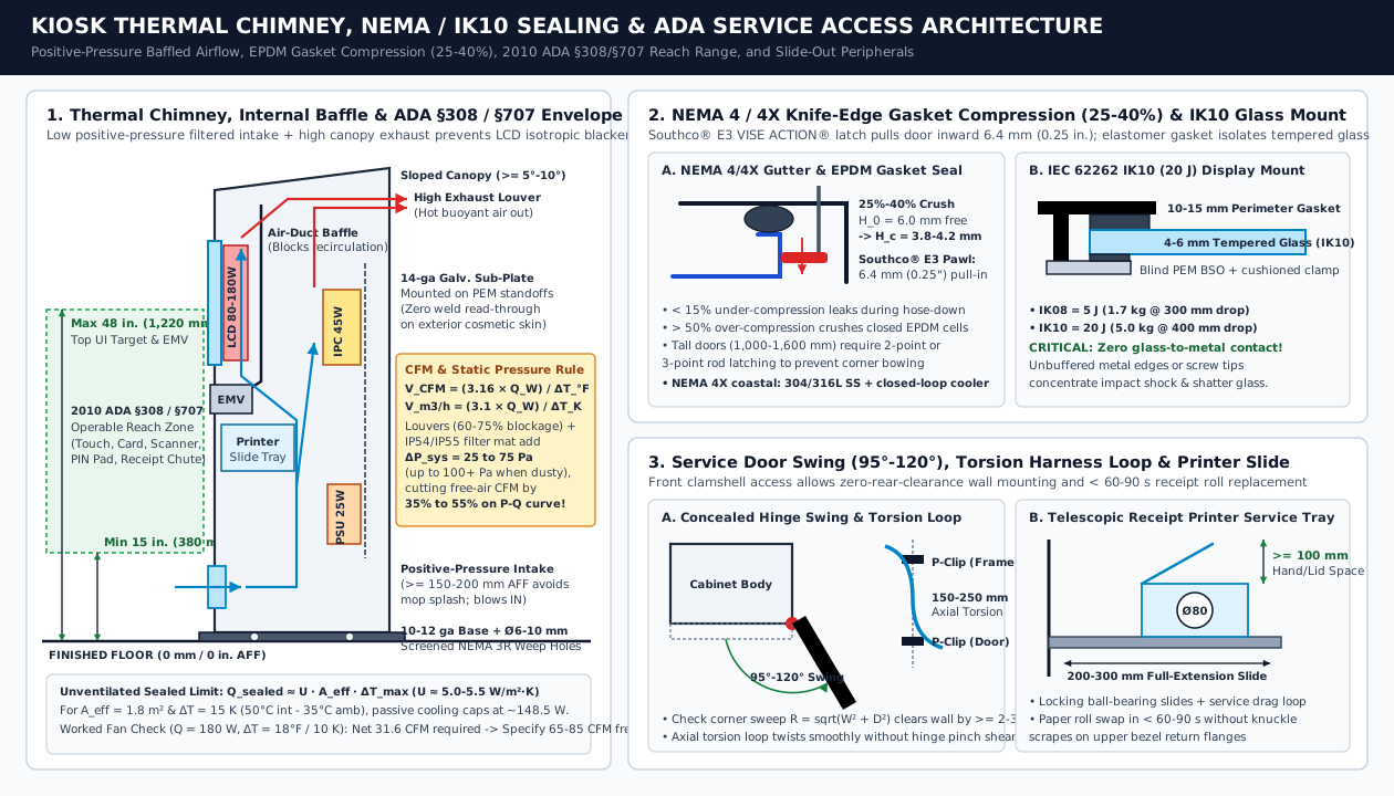
Passive Convection Limit vs. Forced-Air Fan Sizing and Static Pressure Derating
In an unventilated sealed enclosure (U ≈ 5.0–5.5 W/(m²·K)), passive cooling is limited to Q_sealed ≈ U × A_eff × ΔT_max. When heat loads exceed Q_sealed, size forced-air ventilation and derate the fan for filter and louver impedance:
Thermal Chimney & Derated Fan Sizing (Reference Engineering Example — Verify with Fan P-Q Datasheet):
  Passive Sealed Cap (A_eff = 1.8 m², ΔT_max = 50°C int - 35°C amb = 15 K):
    Q_sealed ≈ 5.5 × 1.8 × 15 = 148.5 W maximum passive dissipation.

  Forced-Air Volumetric Flow:
    Imperial (CFM):  V_CFM  = (3.16 × Q_watts) / ΔT_°F   [or (1.76 × Q_watts) / ΔT_°C]
    Metric (m³/h):   V_m3/h = (3.10 × Q_watts) / ΔT_K

  Worked Example (Q = 180 W total, T_amb = 35°C / 95°F, T_int,max = 45°C / 113°F -> ΔT = 10 K / 18°F):
    1. Net airflow required: V_CFM = (3.16 × 180) / 18 = 31.6 CFM (55.8 m³/h).
    2. Static pressure loss: Louvers (60%–75% blockage) + IP54/IP55 filter mat add ΔP_sys = 25–75 Pa
       (rising >100 Pa when dust-loaded), cutting delivered airflow by 35% to 55% along the P-Q curve.
    3. Selection: Specify a 65 to 85 CFM (110–145 m³/h) free-air filter fan to deliver 32 CFM net flow.
Rule of thumb (Positive-Pressure Baffled Chimney): Place the filtered intake fan low (≥ 150–200 mm AFF to avoid floor-mopping splash) blowing into the enclosure, and exhaust at the top canopy. Positive pressure expels air through door seams rather than sucking dust into the touch bezel. Install an internal sheet-metal or 3D-printed baffle to isolate hot LED backlight exhaust from the front liquid-crystal cell, preventing isotropic LCD blackening (“solar clearing”) above 65°C–70°C.
NEMA 250 / UL 50E Ingress and IEC 62262 IK08–IK10 Impact Lookup Table
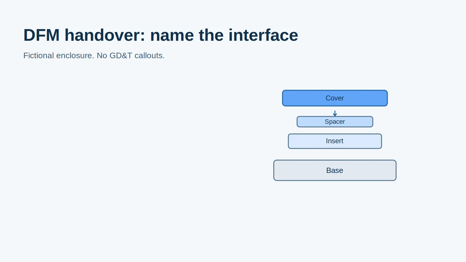
Apply a 1D tolerance stack-up (see our mechanical design engineer DFM handover guide) to control door gasket compression and glass seating across four environmental tiers:
| Rating standard | Deployment environment | Sheet metal seam, gasket & glass DFM rules | Dominant failure mode |
|---|---|---|---|
NEMA 250 Type 1 (~IP20) |
Indoor retail, lobbies, hospitals | Spot-welded 16-ga CRS; open stamped louvers; blocks finger contact (> 12.5 mm) |
Floor-mopping water wicking into unsealed baseplates without a plinth |
NEMA 250 Type 3R (~IP24/34) |
Covered outdoor canopies, parking, drive-thru lanes | Sloped top (≥ 5°–10°), door drip shield, louvered hood + hydrophobic filter, Ø6–10 mm screened bottom weep holes |
Wind-driven rain bypassing unbaffled louvers or condensation pooling in un-drained sumps |
NEMA 250 Type 4 / 4X (~IP65/66) |
Uncovered outdoor plazas, washdown, coastal (4X = 304/316L SS) |
Continuous TIG welds; knife-edge gutter compressing closed-cell EPDM gasket 25%–40% (6.0 mm to 3.8–4.2 mm); blind BSO standoffs; closed-loop cooler |
Hose-down leak (< 15% crush) or permanent cell set and latch overload (> 50% crush) |
IEC 62262 IK08 (5 J) – IK10 (20 J) |
Public self-service touchscreens and payment bezels | 4.0–6.0 mm tempered/chemically strengthened cover glass (5 kg dropped 400 mm = 20 J), cushioned on a 10–15 mm perimeter elastomer gasket |
Tempered glass edge-chip fracture from hard point contact against metal flanges or screws |
Takeaway: Derate filter fans by 35%–55% over V_CFM = (3.16 × Q_W) / ΔT_°F for 25–75 Pa static pressure drop, baffle the LCD backlight plenum, compress closed-cell EPDM gaskets 25%–40% on a knife-edge gutter for NEMA 4/4X sealing, and isolate 4–6 mm IK10 glass from metal contact.
3. Service Access Architecture, Internal Sub-Plates, and 2010 ADA §308 / §707 Ergonomics
- Concealed Hinge Swing (
95°–120°): Wall-mounted kiosks and back-to-back islands require front clamshell service doors on heavy concealed pin hinges (Southco R4/F6orDirak). Verify in CAD that the outer bezel corner sweep radiusR_sweep = sqrt(W_door^2 + D_bezel^2)clears adjacent walls by≥ 2.0–3.0 mm. - Multi-Point Compression Latches (
6.4 mmPull-In): Tall doors (1,200–1,600 mm) bow at the corners if latched only at the center. Dual Southco E3 VISE ACTION compression latches or three-point rod latches pull the door inward by6.4 mm(0.25 in.) after a90°turn, holding uniform30%–35%EPDM gasket crush. - Telescopic Printer Trays (
200–300 mm) & Torsion Loops: Mount80 mmreceipt printers on locking full-extension ball-bearing slides (200–300 mmtravel) with≥ 100 mmvertical clearance above the spindle for< 60–90 sroll swaps. Route door cables through a150–250 mmvertical hinge-axis torsion loop clamped with P-clips so the bundle twists axially instead of pinching. - Removable
14-gaGalvanized Sub-Plates: Mount an internal14-ga(1.90 mm) galvanized steel or mill-finish5052Al sub-plate on blind PEM standoffs to pre-wire the IPC,35 mmDIN rails, and PSUs on the benchtop without weld read-through on cosmetic skins.
2010 ADA Standards (§308 Reach Ranges & §707 Self-Service Transaction Machines)
All operable controls—active touchscreen UI buttons, EMV card reader, PIN pad, barcode scanner, and receipt chute—must sit within the 2010 ADA Standards vertical reach band above the finished floor (AFF), paired with a 30 × 48 in. (760 × 1,220 mm) clear floor space and a 15°–30° screen tilt to prevent ceiling glare for both seated wheelchair users (1,090–1,220 mm eye height) and standing users:
| Reach condition (2010 ADA §308 / §707) | Max height (AFF) |
Min height (AFF) |
Horizontal setback depth | Kiosk hardware & UI placement rule |
|---|---|---|---|---|
Unobstructed Forward or Side Reach (§308.2.1 / §308.3.1) |
48 in. (1,220 mm) |
15 in. (380 mm) |
0–10 in. (0–255 mm) |
Top interactive touch buttons, EMV slot, and receipt chute ≤ 1,220 mm AFF |
Obstructed Forward Reach (≤ 20 in. Counter) (§308.2.2) |
48 in. (1,220 mm) |
Above counter top | ≤ 20 in. (510 mm) |
Requires knee/toe clearance (≥ 27 in. / 685 mm high, 30 in. wide, 17–25 in. deep per §306) |
Obstructed Forward Reach (20–25 in. Counter) (§308.2.2) |
44 in. (1,120 mm) |
Above counter top | 20–25 in. (510–635 mm) |
Recessed countertop kiosks must lower all interactive controls to ≤ 1,120 mm (44 in.) AFF |
Obstructed Side Reach over Shelf (10–24 in.) (§308.3.2) |
46 in. (1,170 mm) |
Above shelf (≤ 34 in.) |
10–24 in. (255–610 mm) |
Applies when reaching sideways across an integrated bag shelf or checkout scale |
Takeaway: Position all operable controls between 15 in. (380 mm) and 48 in. (1,220 mm) AFF (44 in. over deep counters), pull gaskets tight with 6.4 mm compression latches, and mount receipt printers on 200–300 mm slides with axial torsion cable loops.
4. Kiosk Prototyping & Low-Volume Bridge: 3D Printing vs. CNC Machining vs. Sheet Metal
Building an entire kiosk prototype with one process wastes budget and causes structural failures. Large flat 3D-printed panels warp and delaminate along Z-layers under door hinge loads, whereas compound-angled scanner cradles and contoured payment bezels cannot be brake-formed. Extending our comparison of 3D printing vs CNC prototyping and product design stage-gate milestones, allocate each kiosk sub-assembly by geometry and volume:
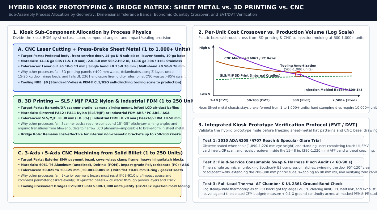
| Kiosk sub-assembly | Recommended process | Dimensional tolerance | Economic volume band | Why alternative processes fail |
|---|---|---|---|---|
Pedestal Body, Doors, Louvers & 14-ga Sub-Plates |
Laser Cut + Press-Brake Sheet Metal (14–16 ga CRS/SS or 2–3 mm 5052-H32 Al + PEM) |
Laser ±0.10–0.13 mm; single bend ±0.25–0.38 mm; multi-bend ±0.50–0.76 mm |
1 to 1,000+ units ($0 hard-tooling NRE) |
3D printing panels > 400 mm warps, delaminates under 20 kg hinge loads, and fails UL 2361 fire rules; billet CNC wastes > 85% swarf |
| Scanner Cradles, Camera Mounts & Lofted Air Ducts | 3D Printing — SLS / MJF Nylon (PA12) or Industrial FDM (ABS / PC-ABS / ASA) |
SLS/MJF ±0.30 mm (±0.3%); Industrial FDM ±0.20 mm (Desktop ±0.50 mm) |
1 to 250 units (production bridge up to 250–500 units) |
Optics require compound 15°–35° pitch/yaw aiming angles and organic lofted blower-to-LCD ducts that cannot be brake-formed |
| Exterior EMV Payment Bezels, Glass Frames & Hinge Blocks | 3-Axis / 5-Axis CNC Machining (6061-T6 Al, Delrin/POM, or impact PC) |
±0.025–0.125 mm with flat ±0.05 mm machined O-ring / gasket seats |
1 to 250 units (bridges until > 500–1,000 units justify $8k–$25k mold tooling) |
Exterior bezels must resist IK08–IK10 pry/impact abuse and seal evenly; printed bezels wick water through porous layers and crack |
Physical Prototype Verification Protocol Before Production Release
Before freezing flat-pattern DXFs and CNC bezel drawings, run three verification checks on the integrated kiosk mule using the session plan and observation log in our physical prototype testing plan:
- ADA §308 / §707 Reach & Glare Trial: Observe seated wheelchair and standing participants completing touch navigation, EMV payment, QR scanning, and receipt retrieval inside the
380–1,220 mm(15–48 in.) AFF band without coaching. - Service Consumable Swap & Pinch Audit (
< 60–90 s): Time a technician unlocking the Southco compression latches, swinging the door95°–120°, extending the200–300 mmprinter slide, swapping an80 mmroll, and confirming zero harness pinch across the torsion loop. - Full-Load Thermal
ΔT& UL 2361 Ground-Bond Audit: Log steady-state thermocouples at the LCD top edge (< 65°C), IPC heatsink, and exhaust louver under full load against the derated CFM budget, and verify< 0.1 Ωcontinuity across all masked PEM ground studs. Browse more manufacturing guides in the DFM and Hardware category.
Takeaway: Pair brake-formed sheet metal for the structural chassis (1–1,000+ units) with SLS/MJF PA12 3D printing for compound-angle internal ducts (1–250 units) and CNC-machined 6061-T6 or polycarbonate for IK10 payment bezels (1–250 units), then verify ADA reach, < 90 s roll swaps, and thermal ΔT on the physical prototype.