Choose SLA when a prototype demands smooth or clear surfaces, thin walls down to 0.2 mm, tight tolerances, or native watertightness for optical and microfluidic checks. Choose SLS when functional hardware needs self-supporting overhangs, zero support marks, durable engineering thermoplastics like Nylon 12 or TPU, and nested low-volume batches without manual support removal.
| Selection factor | SLA (vat photopolymerization) | SLS (selective laser sintering) |
|---|---|---|
| Core feedstock | Liquid thermoset photopolymer resin | Polymer powder (primarily Nylon 12, Nylon 11, PP, TPU) |
| Typical layer thickness | 0.025 to 0.5 mm (Loughborough AMRG) | About 0.1 mm (Loughborough AMRG) |
| Benchmark minimum wall | 0.2 mm (Formlabs Form 4) | 0.3 mm horizontal, 0.6 mm vertical (Formlabs Fuse 1+ 30W) |
| Benchmark dimensional tolerance | ±0.15% to ±0.3% by feature span (Grey Resin V5 at 100 µm) | ±0.5% or 0.3 mm XY; ±1% or 0.6 mm Z (Fuse Series) |
| Support structures | Required; attached to platform and removed manually | None; unsintered powder bed supports all overhangs |
| As-printed surface finish | Smooth, matte or optically transparent | Slightly grainy, uniform matte, inherently porous |
| Primary design failure mode | Support marks on cosmetic faces; UV aging in thermoset resins | Trapped unsintered powder in hollow enclosures lacking escape openings |
How do SLA photopolymer curing and SLS laser powder sintering differ fundamentally?
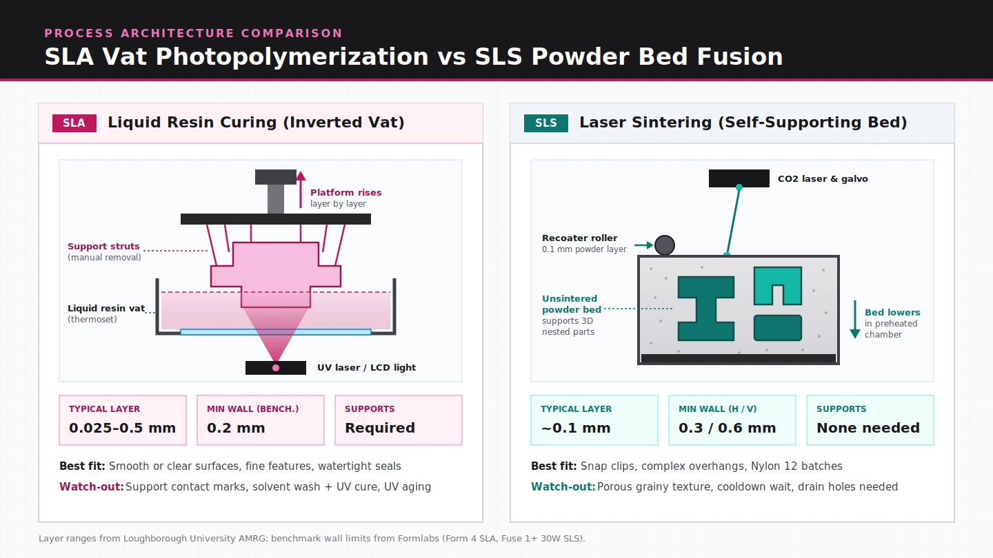
SLA and SLS belong to completely separate additive manufacturing families. Stereolithography cures liquid monomers and oligomers inside a resin vat through photochemical cross-linking driven by ultraviolet light, whereas selective laser sintering uses a high-powered laser to fuse preheated thermoplastic powder particles—typically nylon or polyamide—layer by layer inside a powder bed.
In vat photopolymerization, an ultraviolet laser, digital light projector (DLP), or masked LCD array traces each cross-section of liquid photopolymer resin. Industrial SLA machines commonly print top-down by lowering the build platform into a full vat, while a typical desktop SLA printer inverts the process and cures upward through a transparent vat bottom so the build volume can exceed the liquid volume inside the tank. Because liquid resin offers no structural resistance during printing, SLA parts depend on physical support struts to counter gravity deflection, lateral recoater forces, and bottom-up vat peeling.
In powder bed fusion, a roller or blade spreads a fresh powder layer—typically 0.1 mm thick—across a build platform housed inside a temperature-controlled chamber preheated just below the polymer’s melting point. A laser then supplies the remaining thermal energy to sinter the target cross-section, lowering the bed one layer at a time until the build finishes. Because unfused powder surrounds the growing solid at every height, SLS requires no dedicated support structures and must instead undergo a controlled cool-down period before parts leave the chamber.
Which process achieves tighter dimensional accuracy and finer surface detail?
SLA achieves higher resolution, finer minimum features, and tighter dimensional accuracy than SLS across small-to-medium feature spans. Formlabs benchmark data shows professional SLA resolving 0.2 mm walls and 0.1 mm embossed details, whereas benchtop SLS requires 0.3 mm horizontal and 0.6 mm vertical walls with wider XY and Z tolerance bands.
| Resolution and tolerance metric | SLA (Formlabs Form 4 benchmark) | SLS (Formlabs Fuse 1+ 30W benchmark) | FDM (typical nozzle benchmark) |
|---|---|---|---|
| Typical layer thickness (Loughborough AMRG) | 0.025 to 0.5 mm | About 0.1 mm | 0.178 to 0.356 mm |
| Minimum wall thickness | 0.2 mm | 0.3 mm horizontal; 0.6 mm vertical | About 0.8 mm |
| Minimum embossed detail | 0.1 mm | 0.1 to 0.4 mm (orientation dependent) | 0.6 mm wide by 2 mm high |
| Minimum engraved detail | 0.15 mm | 0.1 to 0.4 mm (orientation dependent) | 0.6 mm wide by 2 mm high |
| Measured XY / feature tolerance | ±0.15% (±0.02 mm min) for 1 to 30 mm; ±0.2% (±0.06 mm min) for 31 to 80 mm; ±0.3% (±0.15 mm min) for 81 to 150 mm | ±0.5% or 0.3 mm (whichever is larger) | Limited by nozzle thickness and extrusion drift |
| Z-axis accuracy | Same continuous layer-cure precision (100 µm test layer) | ±1% or 0.6 mm (whichever is smaller); ±0.5% repeatability | Higher thermal warpage and layer-step error |
Optical precision explains why SLA holds tighter feature edges. Light focused through a laser, DLP projector, or LCD mask cures photopolymer cleanly in XY without mechanical nozzle drag, yielding sharp corners and low-roughness mating faces suitable for small gears, microfluidic channels, and display bezels. In SLS, accuracy depends on laser galvanometer calibration, powder grain size—typically 15 to 100 microns in diameter—and thermal uniformity across the powder bed. Verify critical mating fits with a small test coupon on your target machine before locking tolerances.
How do FDM, SLA, and SLS fit different stages of prototype fidelity?
Across a hardware iteration cycle, FDM handles rapid low-cost shape checks, SLA handles high-detail cosmetic and fluid-tight verification, and SLS handles durable functional assemblies with clips, hinges, and complex internal geometry. Comparing FDM vs SLA vs SLS by test objective prevents over-spending on resolution too early or under-testing snap mechanics on weak layer bonds.
In material extrusion (FDM), molten thermoplastic filament flows through a round heated nozzle in typical layers of 0.178 to 0.356 mm. Because the nozzle radius and diameter constrain corner sharpness and extrusion speed, FDM accuracy and detail stay lower than resin or powder fusion, requiring roughly 0.8 mm walls and 0.6 mm by 2 mm text to stay legible. That makes FDM practical for early volume and ergonomic studies, but unreliable when checking tight mating clearances or small embossed graphics.
When comparing FDM vs SLA directly, SLA eliminates pronounced layer lines and severe Z-axis weakness, giving industrial designers injection-molded smoothness for executive reviews and transparent models. Moving from SLA to SLS then shifts priority from surface polish to thermoplastic toughness and support-free geometry. For the broader five-step workflow that sequences these prints, review the rapid prototyping with 3D printing guide, and once tolerances or metal loads outgrow polymers, move to the 3D printing vs CNC machining comparison.
How do SLA photopolymer resins compare with SLS nylon powders in strength and durability?
SLA produces isotropic, continuous thermoset polymer networks with strong native watertightness, while SLS produces tough, mostly isotropic engineering thermoplastics—principally semi-crystalline polyamides like Nylon 12—that outperform standard resins in impact, chemical, heat, and UV durability. Choosing the wrong chemistry is a leading cause of prototype test failure.
Thermoset cross-linking vs semi-crystalline thermoplastics
SLA liquid feedstocks are thermoset polymers that form covalent bonds across layer boundaries during printing and UV post-curing. Because chemical cross-linking bridges the Z-axis and XY plane equally, SLA parts behave as a continuous isotropic network strong enough for secondary machining or master patterns, with formulations spanning standard, engineering, castable, dental, medical, and biomaterial grades. However, thermoset resins remain sensitive to prolonged UV exposure, and using rigid or brittle general-purpose resin for high-deflection snap clips invites cracking.
SLS sinters familiar engineering thermoplastics—Nylon 12, Nylon 11, glass- or carbon-filled nylon composites, polypropylene (PP), and flexible TPU elastomers. Polyamides dominate SLS because semi-crystalline thermoplastics melt cleanly and deliver lightweight strength, flexibility, and stability against impact, chemicals, heat, UV light, water, and dirt. By contrast, amorphous polymers such as polycarbonate tend to suffer diminished mechanical strength or dimensional accuracy in SLS, limiting their practical use.
Isotropy and watertightness under pressure
Both SLA and SLS avoid the pronounced layer-bond weakness common in FDM, though SLS isotropy varies slightly by powder depending on how long particles retain heat to fuse with the layer below. Watertightness separates the two technologies sharply because SLS surfaces carry residual porosity from powder fusion.
In pressurization testing by the University of Rhode Island Underwater Robotics and Imaging Laboratory cited by Formlabs, FDM robotics enclosures leaked within seconds underwater, SLA enclosures stayed watertight up to very high pressurization levels, and as-printed SLS enclosures kept internal electronics dry only under moderate pressure. Vapor-smoothed SLS enclosures withstood increased pressure by sealing surface pores, and cyanoacrylate coatings or hot isostatic pressing can likewise seal porous SLS skins when fluid resistance is required.
How do support marks, powder drainage, and surface textures affect design rules and post-processing?
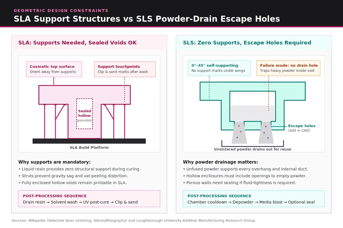
SLA trades extra support cleanup, chemical washing, and UV post-curing for glass-smooth or transparent surfaces, whereas SLS eliminates support marks on complex overhangs from 0 to 45 degrees at the cost of a slightly grainy matte texture and required powder-drain escape openings on every hollow cavity.
SLA support placement, optical clarity, and resin handling
Because SLA cures inside liquid resin, overhanging wings and internal bridges require support structures anchored to the build platform. Placing supports away from critical cosmetic or mating faces minimizes manual clipping and sanding marks after printing. Once a build completes, parts require draining excess resin, an alcohol or ether solvent wash (sometimes followed by a water rinse and scrubbing), drying, and often a final UV post-cure to reach structural strength.
Uncured liquid photopolymers are sticky, messy, and release volatile organic compounds (VOCs), so labs must enforce ventilation and skin protection throughout post-processing. The payoff is surface quality: minimal layer lines keep light from refracting inside clear resins, enabling near-transparent microfluidic blocks, light pipes, and aesthetic covers that closely resemble molded plastics.
SLS self-supporting overhangs, powder drainage, and surface sealing
In SLS, surrounding unsintered powder acts as a built-in cradle throughout the build, enabling 0 to 45 degree overhangs, captive linkages, and embedded conformal cooling channels with uniform surface texture across every face and zero support scars. Post-processing skips support removal entirely and focuses on cooling the cake, recovering loose powder for reuse, and media blasting parts clean.
Two geometric rules still govern SLS parts. First, while SLA and FDM can print completely enclosed hollow voids, SLS cannot empty trapped powder from a sealed chamber; every hollow enclosure requires CAD escape openings so unfused powder drains out cleanly. Second, because SLS finish depends on powder grain size (15 to 100 microns), raw sintered parts feel slightly grainy and porous until secondary finishing—such as media polishing, vapor smoothing, or cyanoacrylate sealing—closes the surface.
How do print speed, cooldown time, and 3D powder-bed nesting change batch economics?
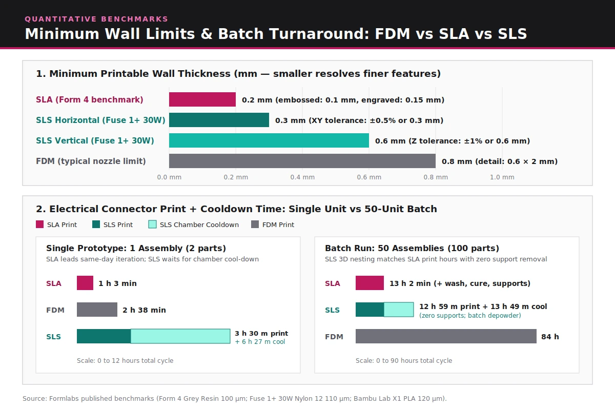
SLA wins same-day single-part iteration because SLS requires tightly controlled thermal staging and long chamber cool-down times, whereas SLS narrows the gap on multi-part pilot batches by nesting assemblies across the full powder volume with zero support removal labor and reusable unfused powder.
| Benchmark part and batch size | SLA (Form 4, Grey Resin, 100 µm) | SLS (Fuse 1+ 30W, Nylon 12, 110 µm) | FDM (Bambu Lab X1, PLA, 120 µm) |
|---|---|---|---|
| Electrical connector — 1 assembly (2 parts) | 1 h 3 min print | 3 h 30 min print + 6 h 27 min cooling | 2 h 38 min print |
| Electrical connector — 50 assemblies (100 parts) | 13 h 2 min print | 12 h 59 min print + 13 h 49 min cooling | 84 h print |
| Gaming controller — 1 assembly (3 parts) | 2 h 36 min print | 3 h 52 min print + 6 h 52 min cooling | 10 h 32 min print |
| Gaming controller — 5 assemblies (15 parts) | 13 h print | 9 h 38 min print + 13 h 47 min cooling | 52 h 40 min print |
On a single prototype, LCD-based SLA cures an entire cross-section simultaneously—meaning added geometric complexity within one layer barely increases print time—and finishes hours before an SLS build cake cools down. SLS heating demands holding chamber temperatures within 2 °C across preheating, melting, and cooling stages with power draw up to 5 kW, creating an unavoidable cooling window before depowdering begins.
When batch quantities climb, SLS workflow economics invert. Because unsintered powder supports stacked layers in three dimensions, engineers can pack dozens of parts into one overnight SLS chamber, reuse unfused powder, and batch-clean the load via media blasting without clipping supports off every piece. Watch one hardware caveat on older monolithic SLS machines: some large systems cap recommended packing density at roughly 8 to 10% to prevent thermal buildup, forcing high powder waste that offsets nesting efficiency.
Which process fits your prototype? SLA vs SLS decision checklist
Match the process to the primary risk your prototype must retire, not to whichever surface looks cleaner on a desk. Use the matrix below alongside your physical prototype testing plan before freezing CAD features or transitioning toward injection molding design rules.
| Prototype part or test goal | Recommended process | Critical design rule to apply | Failure mode avoided |
|---|---|---|---|
| Clear optical window or microfluidic block | SLA (clear photopolymer resin) | Keep walls at or above 0.2 mm and orient supports off optical faces | Light refraction and leaks from grainy or layered walls |
| Pressurized underwater sensor housing | SLA (or vapor-smoothed SLS) | Verify seal grooves within ±0.15% to ±0.3% SLA tolerance span | Seepage through unsealed porous SLS or FDM seams |
| Repeated-use snap-fit enclosure or living hinge | SLS (Nylon 12, Nylon 11, or PP) | Keep horizontal walls at or above 0.3 mm and vertical walls at or above 0.6 mm | Brittle fracture and UV embrittlement in standard thermoset resin |
| Hollow lightweight float or sealed air chamber | SLA (or split-and-bond SLS) | Print sealed cavity in SLA, or add drain escape openings if using SLS | Unremovable trapped powder inside a fully closed SLS enclosure |
| Complex overhanging bracket with internal ducts | SLS (powder bed fusion) | Exploit 0 to 45 degree self-supporting geometry and flush ducts cleanly | Inaccessible internal SLA supports that cannot be clipped out |
| 50-unit functional field-test pilot batch | SLS (nested nylon powder chamber) | Pack chamber densely within machine thermal limits and batch media-blast | High manual support-removal labor across dozens of SLA parts |
Browse more hardware validation and process selection workflows across our prototyping guides.