An industrial design portfolio case study should connect a brief’s constraints to the alternatives, models and physical details that changed the design. A sequence of polished images without those links can fail to explain why the design changed and leave important claims unsupported.
Choose evidence for one project before deciding how to arrange it. Our industrial design portfolio guide covers layout, covers, upload rules and the page template; the task here is deciding which design decisions a single case study can substantiate.
Which case-study approach shows the most useful evidence?
The following comparison describes editorial choices for a physical-product story. It is not a scoring system used by a school or employer.
| Approach | What the reader sees | What the reader can judge | Dominant Failure Mode & Prevention |
|---|---|---|---|
| Final-image showcase | Resolved form and finish intention | Visual outcome | Reasoning is hidden; attach the constraint and decision behind a detail |
| Complete chronological archive | Every sketch and model in date order | Volume of activity | Important changes disappear in repetition; select the evidence that explains a choice |
| Decision-led case study | Constraint, alternatives, model question, detail and reflection | How evidence affected the design | Claims outrun the evidence; label assumptions, limits and unresolved questions |
ArtCenter’s Product Design portfolio guidance, opened on 19 October 2026, asks projects to include objectives and user context, sketches exploring different directions and mechanical functionality, rough prototypes or models, and final renderings or a model. It also calls for attention to sustainability. The sequence below is our editing method for connecting such material; it is not an additional ArtCenter requirement.
Start with the constraints that could change the design
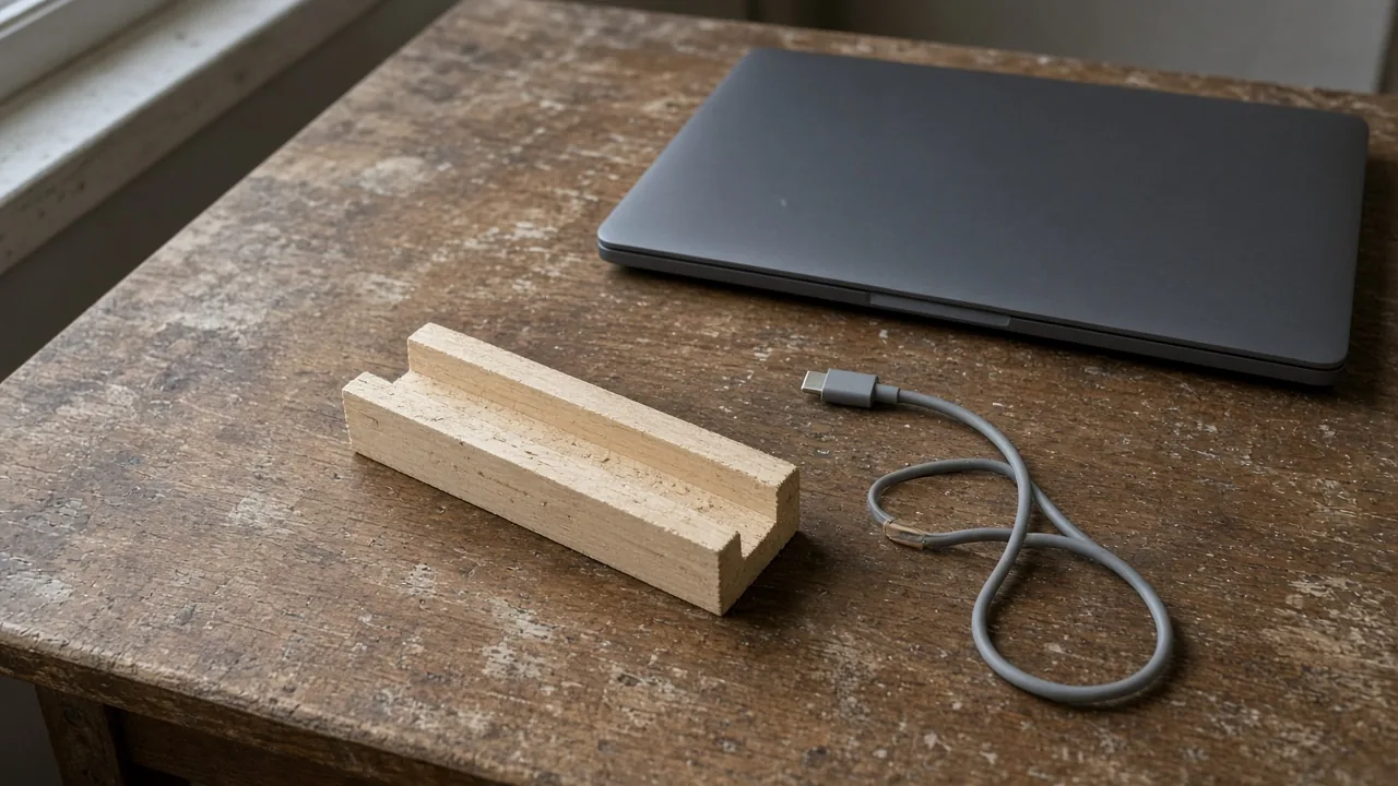
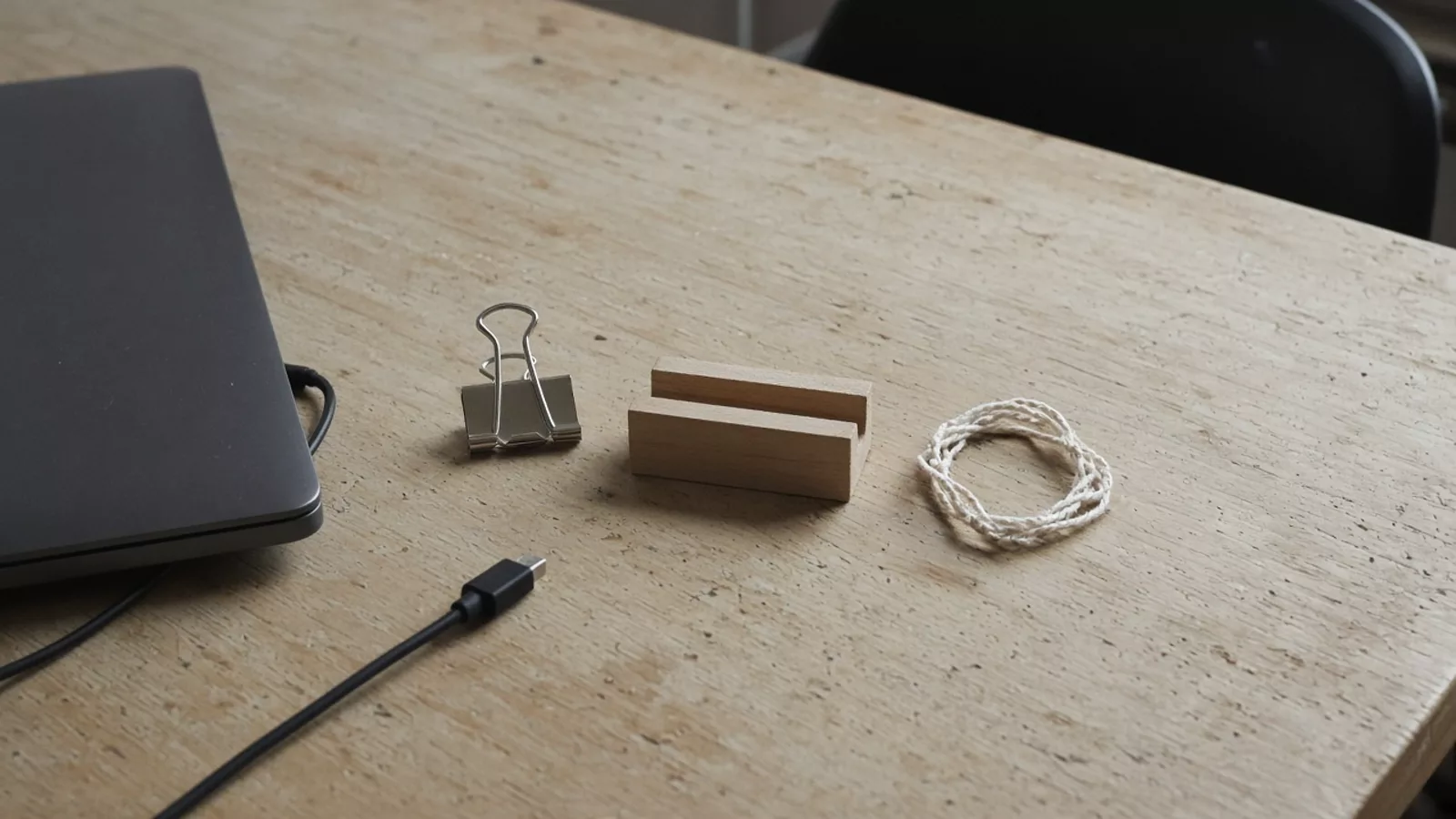
Use a fictional removable cable holder for a shared desk. Its brief asks the designer to keep the cable accessible, leave space beside a closed laptop, and allow removal of the internal insert. These constraints give the reader a reason to care about the later sketches and assembly detail.
Write the constraint and its consequence together. “Must fit the available desk area” becomes useful when it is paired with the measured envelope from your own project. “Must allow insert removal” leads to an access route that can be shown in a model or section. If the limit is still unknown, identify how you would establish it instead of inventing a test result.
For this fictional study, the evidence labels would be:
- C1, desk envelope: A sketch of the permitted footprint and adjacent laptop position, with dimensions taken from the actual project when available.
- C2, cable access: The intended one-handed action, identifying where the hand approaches and where the cable exits.
- C3, insert removal: A drawing of the path by which the insert leaves the holder, including the tool access question.
State your own role alongside these constraints. If another team member conducted observations or made the model, identify that contribution at the relevant evidence item. This makes the scope of your design decision understandable.
Show sketch divergence as competing answers to the same brief
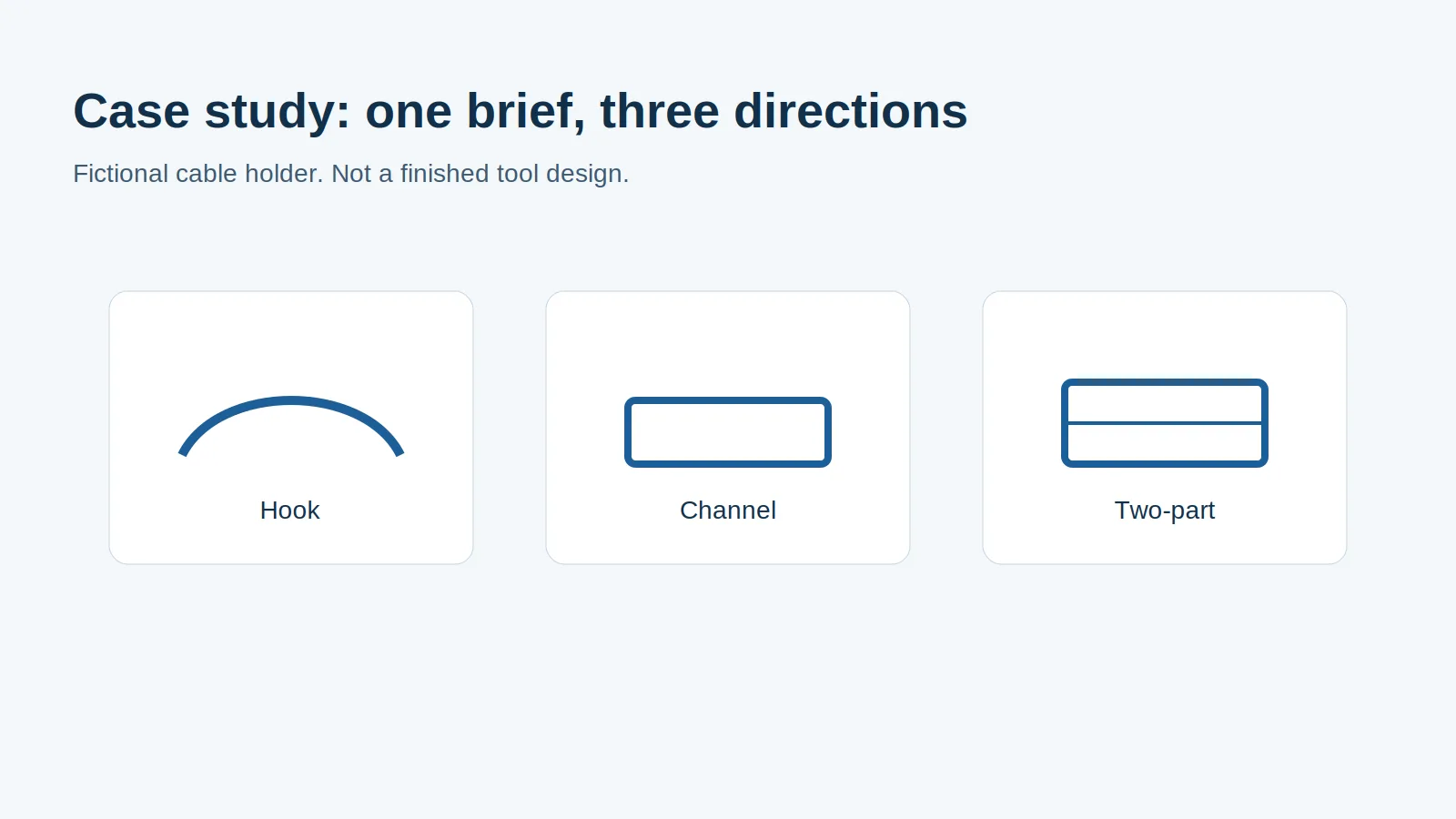
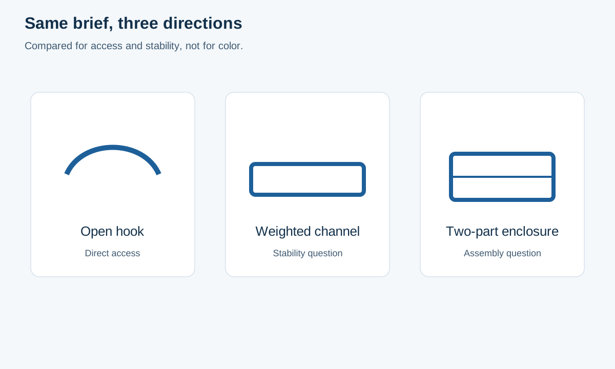
For the cable holder, compare an open hook, a weighted channel and a two-part enclosure with a removable insert. These are meaningfully different approaches: one prioritizes direct access, another explores stability, and the third makes internal access an assembly question. Changing color or corner radius alone would not explain that choice.
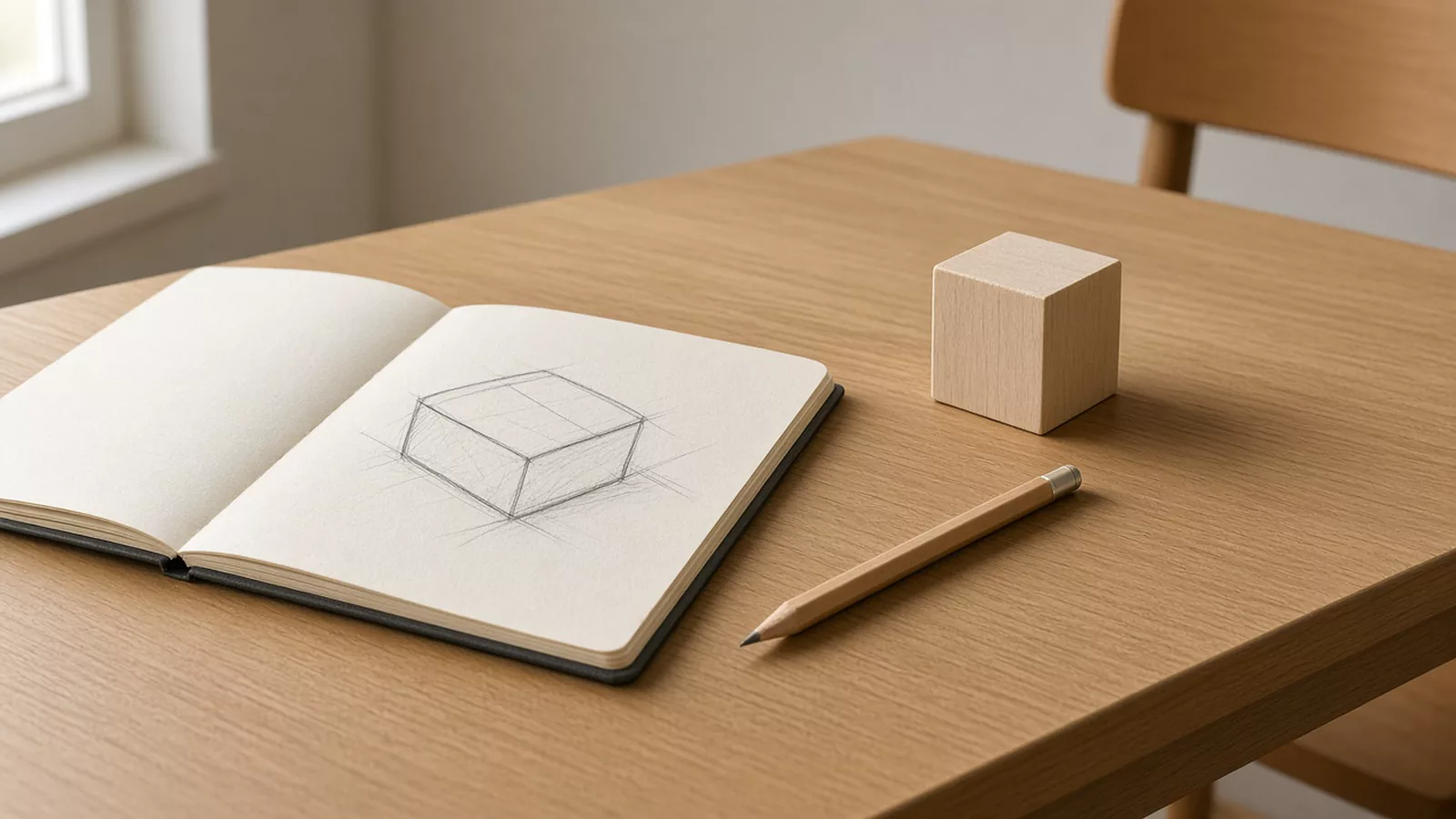
Select sketches that make the differences visible. Add a short reason to investigate or reject each direction against C1, C2 or C3. A rejected sketch earns its place when it reveals a tradeoff that survives into the final design.
Avoid inventing a tidy path after the project has finished. If the two-part enclosure was selected before access was checked, say so. A later model that exposes the weakness can explain a revision more clearly than a claim that the first sketch solved everything.
Give the foam or appearance model one explicit question
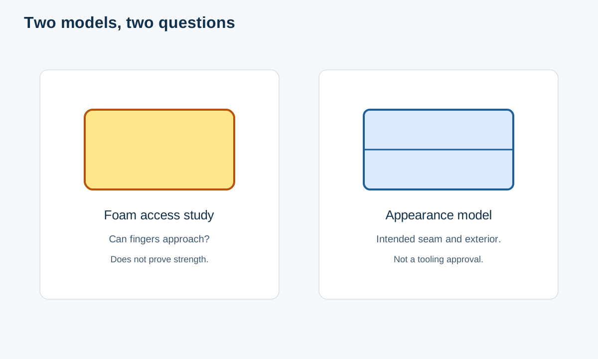
Make the model’s purpose legible before showing its finish. A foam study might explore whether the form leaves room for fingers to approach the cable. An appearance model might show the intended seam, texture contrast or visual relationship to the laptop. Label which kind you are presenting.
For a real project, pair the model with a record of what you actually examined. A useful caption identifies the question, the observed result and the resulting change. If no test took place, describe the model as a form study and explain the planned check. Do not convert an attractive model into evidence of comfort, strength or manufacturability merely by using stronger language.
For example, a project record could support this kind of statement: “The access study showed contact at the rear edge during the documented approach; the next revision opened that edge.” That is an example of caption structure, not an observation from this fictional project. Use your own evidence and describe the conditions under which it was collected.
Keep the model’s limits beside its contribution. In this example, a foam shape does not establish the production material’s strength, the proposed molding process’s capability or the assembly’s service life. Those claims need different evidence.
Resolve the story through a parting-line or assembly detail
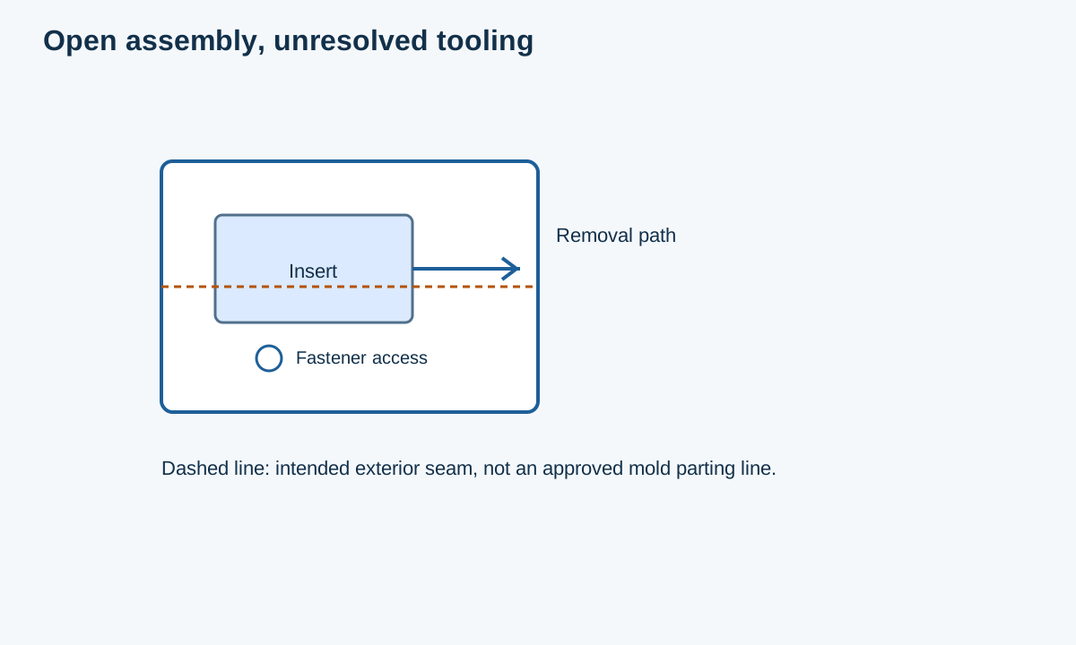
The case study now needs a detail that follows from the earlier choice. For the two-part cable holder, show an open assembly with the insert removal path and access to the fastener. Connect it to C3: the reader should be able to see what must move first and whether the intended tool can reach it.
Distinguish an intended exterior seam from a proposed mold parting line. A line drawn on a rendering communicates appearance; deciding how the mold divides requires manufacturing review. If your case study only contains the appearance proposal, label it accordingly rather than presenting it as an approved tooling solution.
If the detail involves molded walls or draft, link the actual check or annotated section. Our injection molding design rules explain that manufacturing review. A portfolio detail needs enough information to reveal the design decision; a full supplier handover belongs in the manufacturing specification checklist.
End the detail discussion by identifying what changed and what remains unresolved. “Insert access is shown; repeated removal has not been tested” is a useful boundary when it matches the project record. It gives the next development step a concrete purpose.
Audit the claims before choosing the final evidence
Use a small evidence audit to catch gaps in the story. This is our editorial check, not a school assessment formula. Count a decision as supported only when the linked item addresses that specific claim; a final rendering does not automatically support every claim about the product.
Suppose a fictional draft claims four decisions: footprint, cable approach, insert removal and repeated-assembly durability. Suppose it links a footprint overlay, a documented access study and an assembly section, but contains no durability test. Its worked coverage calculation is:
Evidence coverage = decisions with linked evidence / decisions claimed × 100%
Evidence coverage = 3 / 4 × 100% = 75%
The percentage identifies an editing gap, not overall design quality. Change the unsupported durability statement to a planned test, or add a real test record if one exists. Do not fill the gap with another image that answers a different question.
Rule of thumb — evidence threshold: Every claimed design decision needs at least one visible supporting item. If that count falls below one, soften or remove the claim, or add the missing evidence. This is our suggested editing threshold, not an application rule.
The resulting case study lets a reader follow the constraints, compare the sketch alternatives, understand the model’s purpose, and inspect one consequential physical detail. Close with what the evidence changed and the next unresolved question. This article’s cable holder is an invented teaching example; a finished portfolio should make the same distinctions using the student’s own work.